Progressive path tracing
Field's progressive path tracer lets you light a scene with materials, reflections and environment maps, then watch the image settle as samples accumulate. The examples below build scenes you can change and render yourself.
PathTracingRenderer runs on
Vulkan compute devices, including MoltenVK on macOS. When Field has enabled VK_KHR_ray_query,
AUTO selects hardware triangle traversal. Both backends share lighting, material evaluation and
accumulation code. The Renderers reference covers the types used here.
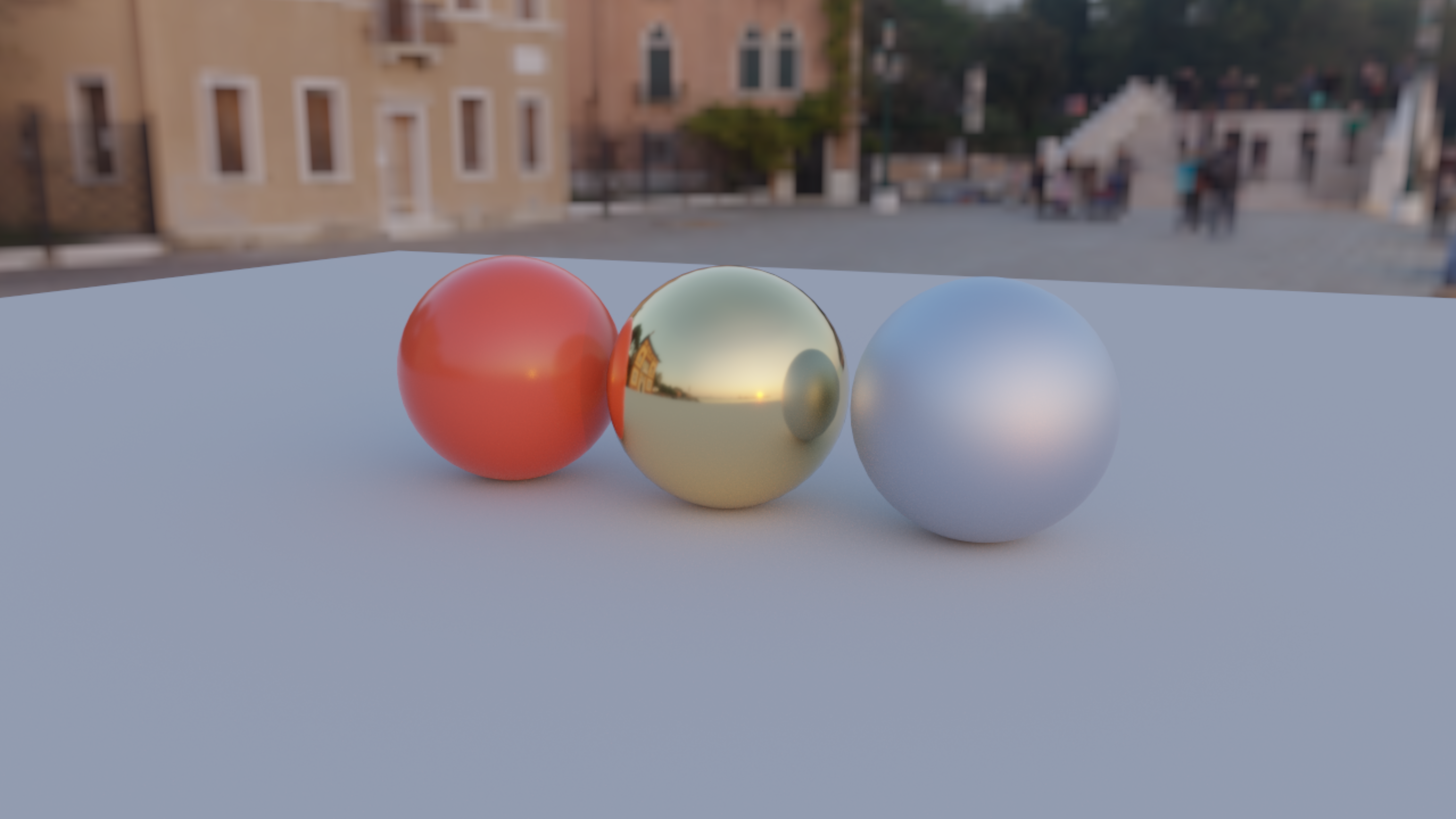
Environment: Venice Sunset by Greg Zaal / Poly Haven (CC0), from the existing Fabricate demo assets.
Start with the material study
Create a child box beneath an existing renderer box, then run the code below.
It traces three spheres over a floor using the bundled Venice sunset OpenEXR
map. Rerunning the box automatically replaces its previous tracer; no cleanup
coroutine is needed. The environment path is relative to the Field checkout.
See the graphics guide for setting up renderer boxes.
The two opaque material studies opt into indirectClamp = 10f; the glass study leaves
clamping disabled so its transmitted lighting and caustics are preserved.
import afield.graphics.scene.fabricated.*

val tracer = PathTraceDemo.install(
    renderer,
    "public/docs/assets/fabricate_demo/venice_sunset_1k.exr",
)
tracer.samplesPerFrame = 1
tracer.maxBounces = 5
tracer.indirectClamp = 10f // optional: reduces indirect fireflies, with some bias
tracer.blitToScreen() // separate pass sampling tracer.output
The checkout also includes a complete renderer-and-scene example in
dev_docs/agents/transcripts/path_tracing_materials.yaml, which can be run as an
OperationTranscript.
For an explicit backend comparison, pass backend to the demo installer:
val tracer = PathTraceDemo.install(
    renderer,
    width = 1280,
    height = 720,
    backend = PathTracingRenderer.Backend.RAY_QUERY,
)
tracer.blitToScreen()
println(tracer.backend)
RAY_QUERY fails with a capability error when unavailable; AUTO falls back to COMPUTE_BVH.
Re-running the installer replaces the named tracer and retires its previous GPU resources.
Supply your own scene
Build geometry in world coordinates. Colours are linear RGB. For opaque materials, metallic controls the dielectric/metal mixture, and roughness controls isotropic GGX. Opaque roughness zero uses a small finite roughness floor. Glass has a true specular reflection/refraction mode at zero roughness.
import afield.graphics.scene.fabricated.*
import afield.graphics.vulkan.util.Camera

val scene = PathTraceScene()
val paint = scene.material(PathTraceMaterial.plastic(0.7f, 0.08f, 0.02f))
val gold = scene.material(PathTraceMaterial.metal(0.95f, 0.7f, 0.3f, 0.15f))
scene.sphere(Vector3f(-1f, 1f, 0f), 1f, paint)
scene.sphere(Vector3f(1f, 1f, 0f), 1f, gold)

/*
scene.mesh(positions, triangleIndices, paint, optionalVertexNormals)
scene.triangle(a, b, c, paint)
scene.quad(a, b, c, d, paint)
*/

val env = PathTraceEnvironment.fromFile("/absolute/path/studio.exr")
val camera = Camera(renderer).also {
    it.at.set(0f, 2f, 7f)
    it.target.set(0f, 1f, 0f)
}
val tracer = PathTracingRenderer(
    renderer,
    scene,
    env,
    width = 1280,
    height = 720,
    camera = camera,
).install()
PathTraceEnvironment accepts OpenEXR, Radiance HDR, STB-supported ordinary image
files, or a linear RGBA FloatArray. LDR files are converted to linear floats by
STB. Maps are equirectangular: north at the top; longitude is atan2(z, x).
environmentRotation rotates the map around Y in radians, and
environmentIntensity scales its radiance. Construction copies scene and map data.
Recreate the tracer after geometry, CPU material or map changes. Shader material
functions can instead be edited and reloaded in place, as below.
Camera, jitter and depth of field
The tracer uses an ordinary Field Camera: at, target, up and p.fov control
the view. You can share it with rasterized geometry, animate it, or attach the usual
keyboard controls. The tracer uses perspective projection and its own output aspect
ratio; SuperProjection orthographic blending and principal-point offsets are not used.
val camera = tracer.camera
camera.at.set(0f, 2.6f, 8f)
camera.target.set(0f, 0.65f, 0f)
camera.p.fov = 0.62 // vertical field of view, in radians
var cameraKeys by keyCamera(renderer = renderer, camera = camera)

tracer.pixelJitter = 1f
tracer.apertureRadius = 0.25f
tracer.focusDistance = null // follow the target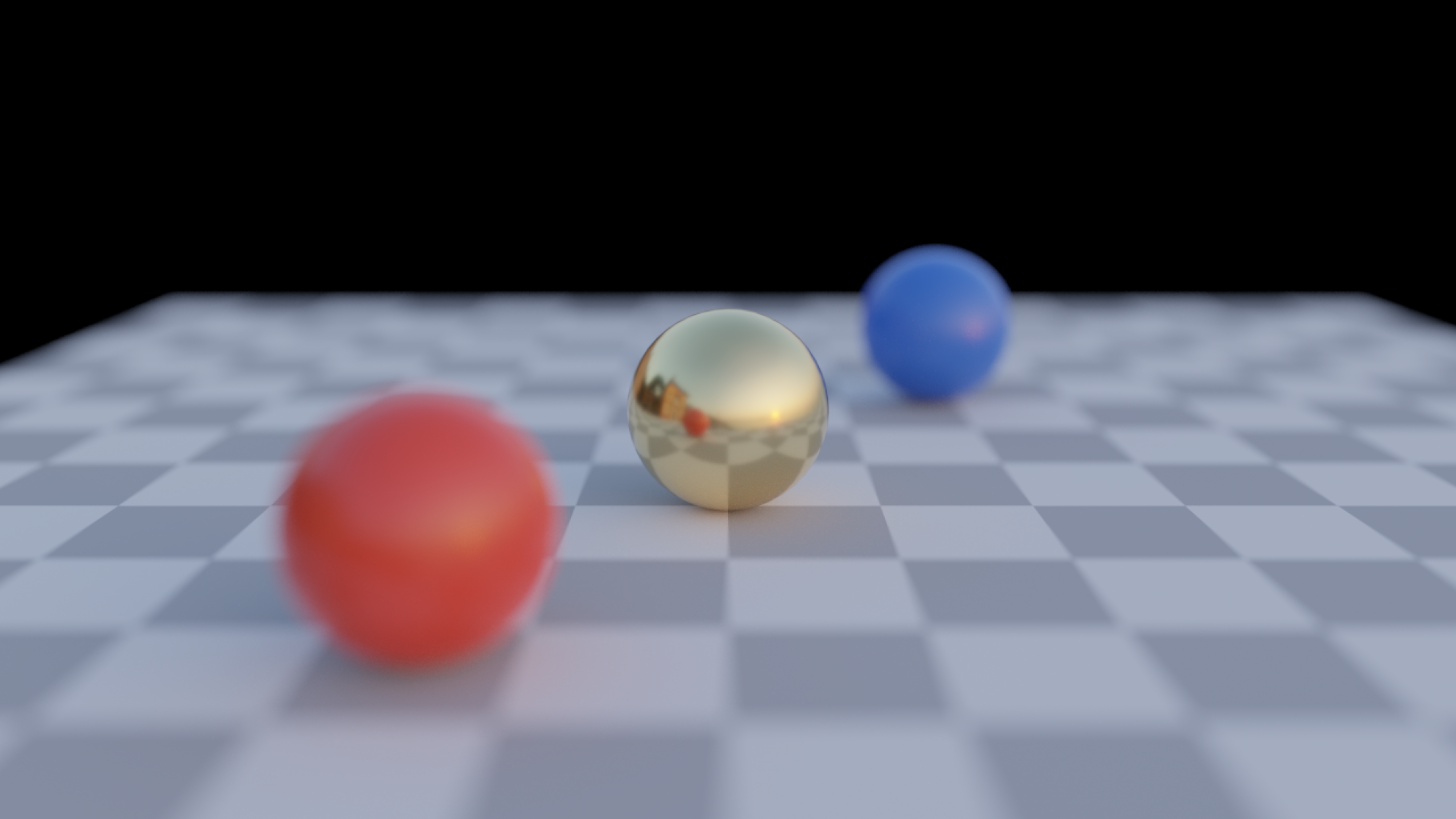
| Control | Default | Meaning |
|---|---|---|
pixelJitter |
1f |
Samples the full pixel footprint for antialiasing. 0f samples its centre; values between zero and one narrow the footprint. |
apertureRadius |
0f |
Circular lens radius in world units. Zero disables depth of field; larger values increase defocus blur. |
focusDistance |
null |
Tracks the camera target. Set a positive distance in world units to hold focus independently of the target. |
tracer.focusDistance = 5f // focus plane five world units along camera.forward
tracer.apertureRadius = 0.08f // a smaller opening gives subtler blur

// tracer.apertureRadius = 0f // pinhole view again
Focus is a plane perpendicular to the viewing direction, so off-axis objects at the
same depth remain sharp. This uses a thin-lens camera model:
each path starts at a sampled point on the circular lens and aims at that plane.
Aperture changes blur without changing exposure. Lens samples use their own two
Sobol dimensions, independently of pixel and lighting samples; depth of field still
converges when pixelJitter is zero.
By default, pose, FOV, jitter, aperture and focus changes reset accumulation before the next sample. Enable temporal reuse to retain compatible surface history on camera movement. With automatic focus, moving only the target nearer or farther still resets accumulation, even if the viewing direction is unchanged. If sampling is paused, the new view appears when you resume. Scaling a scene calls for scaling its aperture and explicit focus distance too. This models a circular aperture; it does not simulate shutter motion blur, diffraction or a multi-element photographic lens.
Loading glTF and GLB models
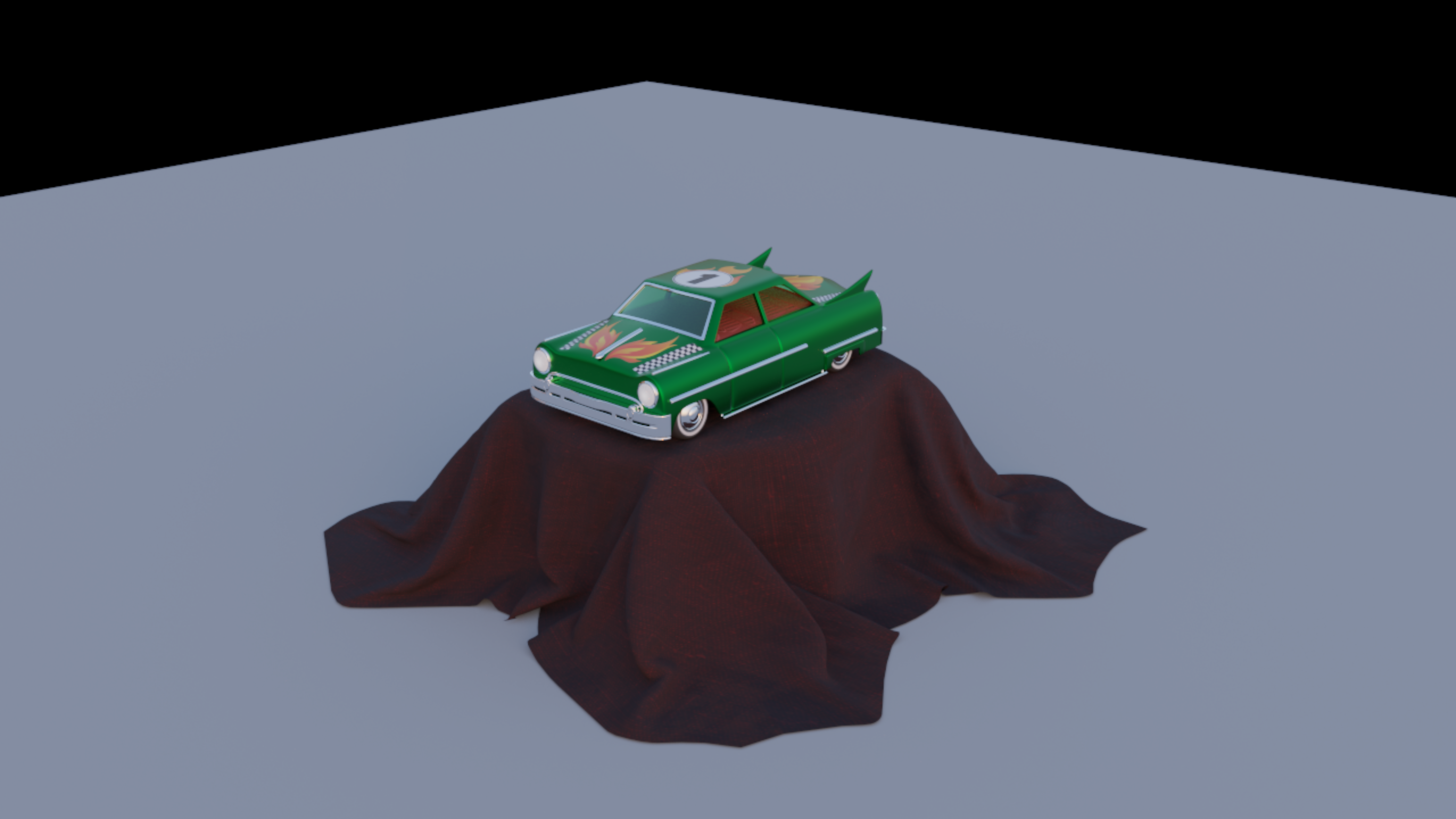
Load a static glTF 2.0 scene before creating the tracer:
import afield.graphics.scene.fabricated.*

val scene = PathTraceScene.fromGltf("/absolute/path/model.glb")
val tracer = pathTracingHere(scene, env, camera = camera)
tracer.indirectClamp = 10f
tracer.blitToScreen()
Both .gltf with external buffers/images and .glb with embedded images work.
The import copies the default scene's node hierarchy into world-space triangles,
including repeated mesh instances, mirrored transforms and inverse-transpose
normals. It needs no live renderer. Geometry is a static snapshot; recreate the
tracer after importing another model or changing its geometry.
To add a model alongside other geometry, use scene.importGltf. Its result
provides world-space bounds, a name-to-material-ID map and import warnings:
val scene = PathTraceScene()
val model = scene.importGltf(
    "/absolute/path/model.gltf",
    transform = Matrix4f().translate(0f, 1f, 0f).scale(2f),
)
val center = Vector3f(model.boundsMin).add(model.boundsMax).mul(0.5f)
val radius = model.boundsMin.distance(model.boundsMax) * 0.5f
camera.target.set(center)
camera.at.set(center).add(radius * 2.3f, radius * 1.4f, radius * 2.7f)
Model units are preserved. Choose a scale and rayEpsilon appropriate to the
model: the default epsilon is 0.0001 world units. The bundled Toy Car example
scales the small source model by 20 and fits the camera to its imported bounds.
| Imported feature | Path-tracer behavior |
|---|---|
| Base colour, metallic and roughness | Factors multiply their textures; metallic uses blue and roughness uses green. |
| Base-colour and emissive images | sRGB RGB is decoded to linear light; alpha remains linear. |
| Vertex colours | Multiply base colour and coverage. |
| Normal maps | Tangent frames are reconstructed from each triangle's transformed UVs; normal scale is applied. |
| Texture coordinates and samplers | Per-texture UV channels, baked KHR_texture_transform, repeat/clamp/mirrored repeat, nearest or bilinear magnification. |
OPAQUE, MASK, BLEND |
Opaque coverage, cutoff-tested holes, or stochastic alpha coverage, including shadow rays. Alpha blend does not refract light. |
| Emission | Emissive factors, textures and KHR_materials_emissive_strength. |
| Transmission, IOR and volume | Mapped approximately to the tracer's glass models; see the limits below. |
You can amend materials during import, and then edit them through the same
shadeMaterial hook as a hand-built scene:
val model = scene.importGltf(
    "/absolute/path/model.glb",
    material = { name, imported ->
        if (name == "Glass")
            imported.copy(
                transmission = true,
                metallic = 0f,
                thinWalled = false,
                roughness = 0.08f,
                ior = 1.5f,
            )
        else imported
    },
)

// model.materialIds["Glass"] selects that material in surface.materialId.
Textures and vertex colour are applied before shadeMaterial; surface.uv
contains the base-colour texture's UV, and surface.color contains interpolated
vertex colour. Material reload and named replacement work as for other scenes.
This first importer supports static meshes. Skins and morph targets are rejected; node animations are reported and the default pose is imported. Clearcoat, sheen, specular extensions, texture compression and unlit shading are not evaluated. Unsupported required extensions fail the import; unsupported optional extensions produce warnings. Toy Car uses optional clearcoat and sheen, so this example shows their base-material fallback. Its model and attribution are in the Fabricate demo assets.
There are no texture mipmaps or anisotropic filtering yet, and reconstructed normal-map tangents may differ from an asset's authored tangent frames. Baked ambient-occlusion maps are not applied. Partial transmission is approximated as full dielectric transmission, and transmission textures are not evaluated. Smooth zero-volume materials become thin panes; rough transmission uses solid glass and needs closed geometry. Volume absorption uses actual mesh thickness and world-space attenuation distance; nested media remain unsupported.
Colour, texture-channel and coverage conventions follow the glTF 2.0 specification.
Scene ownership and render-to-texture
install() registers under name = "path-tracer" by default. Installing another
tracer with that name detaches and retires the old one, including its presentation
pass. An old handle's close() cannot remove its replacement. Use distinct names
for independent tracers. A setup box can finish immediately; the scene keeps
rendering until replacement or explicit tracer.close().
The renderer schedules compute, then resolves into tracer.output before the
screen passes. The output is an ordinary RenderToTexture with linear,
premultiplied HDR RGBA. Sample it in your own Field module, post-process it, or
call tracer.blitToScreen() for aspect-preserving exposure/Reinhard presentation.
tracer.output.blitToScreen() is also available when Field's ordinary blit/color
grade is desired; it does not apply the tracer's Reinhard curve. When registering
that helper directly, give it a stable name so subsequent helper calls replace it.
To render into an existing RTT, pass target = rtt and matching width and
height to the constructor or pathTracingHere. It needs one floating-point color
attachment and must belong to the same renderer. The tracer schedules this RTT;
do not schedule it a second time. close() removes the tracer's resolve module
without disposing a caller-owned RTT.
Environment lighting without a visible sky
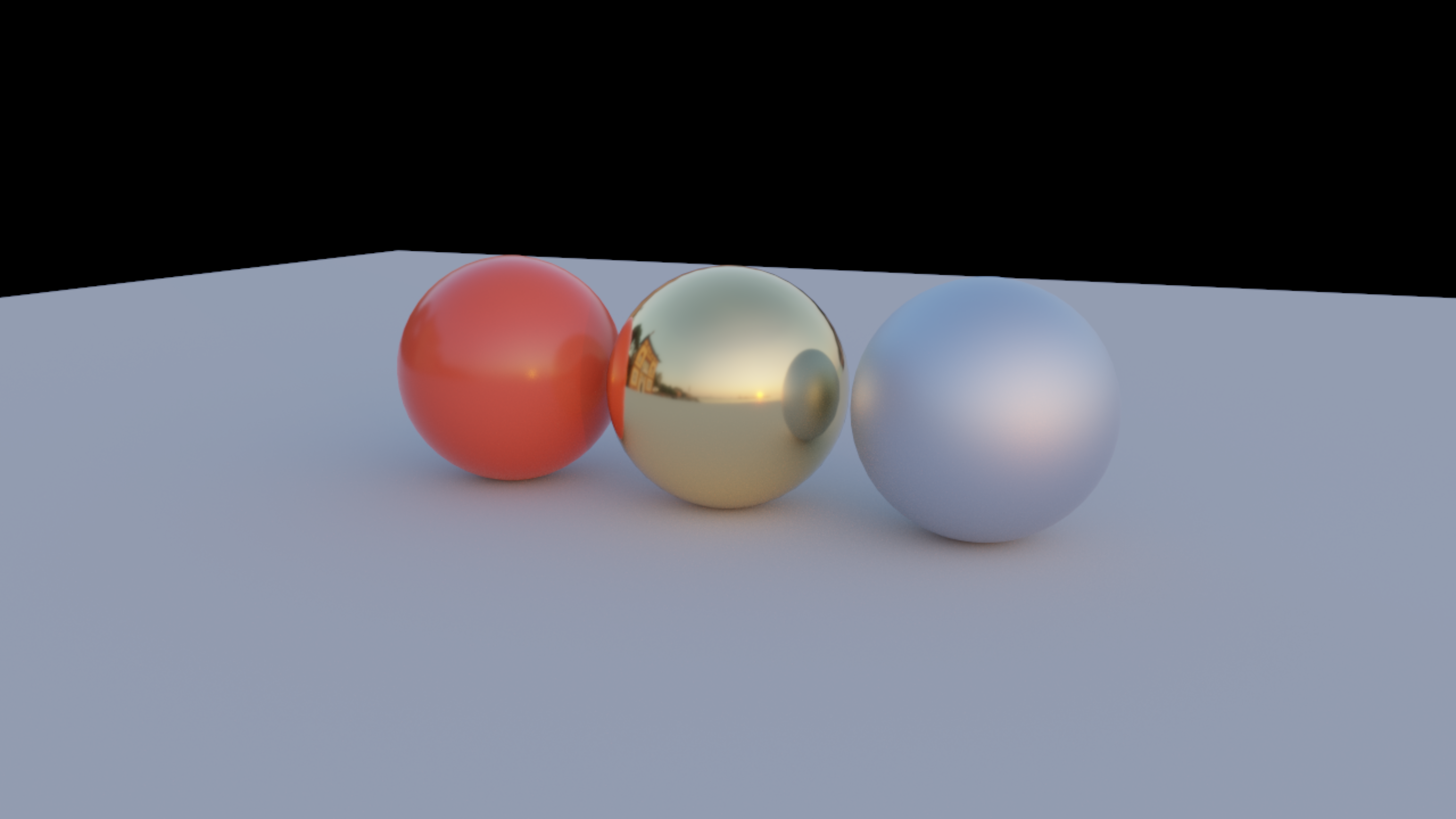
tracer.showEnvironment = false
// Default background is opaque black. Choose any linear RGBA color:
tracer.background = Vector4f(0.02f, 0.02f, 0.02f, 1f)
// Or make empty pixels transparent for compositing:
tracer.background = Vector4f(0f, 0f, 0f, 0f)
tracer.blitToScreen(blend = true)
Only camera rays that miss their first surface see this background. The environment still illuminates objects and remains visible in reflections and through refracting surfaces. Changing either background control resets accumulation. This is a useful art-direction/compositing control; it does not change the environment's radiance.
Depth fog
Blend distant surfaces toward a colour, with a clear region around the camera. This is a
curve applied to a finished sample, not a medium light travels through — if you want shafts,
a lamp that glows, or shadows cast into the air, you want a participating
medium below, and the table there compares the two directly.
fogDensity remains the cheaper choice when you only need distance haze.
tracer.fogColor = Vector3f(0.25f, 0.35f, 0.5f)
tracer.fogDensity = 0.1f
tracer.fogStartDistance = 5f
tracer.fogBackground = true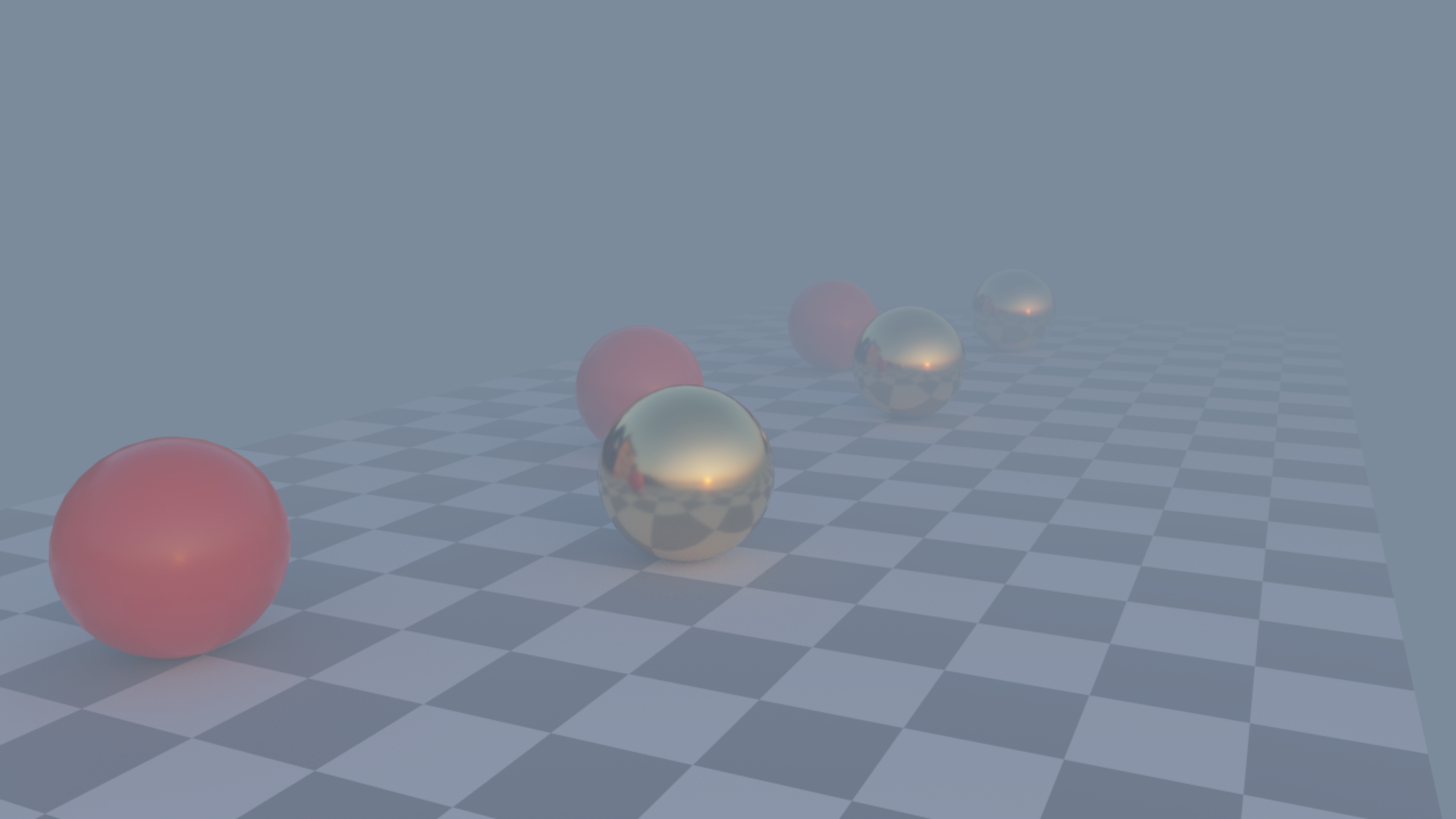
| Control | Default | Meaning |
|---|---|---|
fogDensity |
0f |
Nonnegative density per world unit. Zero disables fog. |
fogStartDistance |
0f |
Nonnegative clear distance before fog begins. |
fogColor |
Vector3f(0.5f, 0.5f, 0.5f) |
Linear HDR colour, before exposure and display tone mapping. Assign a new vector to change it; the getter returns a copy. |
fogBackground |
true |
Treat primary-ray misses as infinitely distant. Set false to preserve the camera-visible environment or background colour. |
At distance d, the surface contribution is multiplied by
exp(-fogDensity * max(d - fogStartDistance, 0)); the remaining weight comes from
fogColor. Distance is measured from the camera centre to the first visible hit,
in world units. Fog is applied per path sample, so jitter and depth-of-field
coverage still accumulate normally. Changing any fog control resets accumulation.
Fog preserves premultiplied alpha. A transparent hidden background remains
transparent; an opaque background or visible environment fades fully to the fog
colour when fogBackground is enabled. Environment lighting remains unchanged.
This is an artistic depth effect, not volumetric scattering: it does not create light shafts or march through a medium. A mirror or glass surface uses its first-hit distance, rather than distances along subsequent reflected or refracted rays. Temporal history stores unfogged colour, then applies the current camera distance when reprojecting it; moving out of dense fog can reveal retained surface detail.
For light shafts, and for haze that dims the light arriving at a surface as well as the light leaving it, use the medium in the next section. The two controls are independent; enabling both attenuates whatever the camera sees first twice over.
A participating medium
mediumDensity fills the scene, or a box within it, with uniform haze that light
scatters through. It works differently from fogDensity above:
| Property | fogDensity |
mediumDensity |
|---|---|---|
| what it does | blends the finished radiance of a sample toward fogColor |
samples a collision distance along every ray segment |
| what it knows | the primary hit distance | the whole path, and every light connection along it |
| light reaching a surface | unchanged | attenuated over its own length |
| a lamp inside it | unchanged | glows |
| a slat between a lamp and the haze | nothing | casts a shadow into the haze |
| cost | a multiply | one distance sample per segment, two shadow rays per collision |
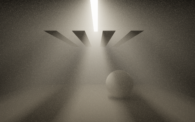
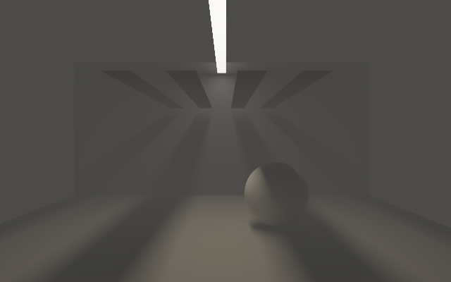
The same geometry twice: mediumDensity = 0.16 above, fogDensity = 0.16 with a grey
fogColor below, both at 1536 samples per pixel. The slats' shadows reach the wall and the
floor in both; the difference is in the air, which the medium lights unevenly and
fogDensity paints one flat grey.
How the two images were compared
Over the 100920 pixels of that frame whose primary ray hits no geometry at all,
the medium gives a mean radiance of 0.91481 with a spatial standard deviation of
2.02372; fogDensity gives 0.34068 with a deviation that prints as 0.00000, because a
background miss has no depth for a depth curve to act on. With neither, both figures
are exactly zero. Both images come from PathTraceMediumGpuSmoke.godRays, which
asserts the medium's deviation against a floor (mediumSpread > 0.5) and
fogDensity's variation relative to its own mean (fogSpread / fogMean < 1e-4); the
relative test allows for float32 accumulation over 100 000 pixels.
/*
The room is the medium's extent. Bounds are not decoration: an unbounded medium has
zero transmittance to infinity, so an environment map becomes unreachable and an
environment-lit scene renders black.
*/
tracer.mediumBounds = Vector3f(-6f, 0f, -3.9f) to Vector3f(6f, 5.2f, 3.9f)
tracer.mediumDensity = 0.16f // extinction per world unit
tracer.mediumAlbedo = Vector3f(0.96f, 0.95f, 0.93f) // how much of that scatters
tracer.mediumAnisotropy = 0.4f // forward-scattering, in (-1, 1)
tracer.maxBounces = 8 // a collision spends one of these| Control | Default | Meaning |
|---|---|---|
mediumDensity |
0f |
Extinction — scattering plus absorption — per world unit. Zero disables the medium. Achromatic, so a distance sample stays one decision; colour comes from the albedo. |
mediumAlbedo |
Vector3f(1f, 1f, 1f) |
The fraction of extinction that scatters rather than absorbs, per channel. One conserves energy exactly; zero is pure Beer–Lambert absorption with no glow at all. The getter returns a copy. |
mediumAnisotropy |
0f |
Henyey–Greenstein g, in (-1, 1). Zero is isotropic, positive forward-scatters into a halo, negative throws light back toward the camera. |
mediumBounds |
null |
The axis-aligned box the medium fills, as low to high. null fills all space, with the consequence above. |
Changing any of them resets accumulation.
A medium uses up bounces. A collision in the medium is
an interaction like a surface hit, and it spends one of maxBounces. A medium dense
enough to scatter a path three or four times therefore has that many fewer bounces
left for surfaces, and a dense enough medium makes the image darken rather than
brighten, because the bounce cap is discarding energy. Raise maxBounces (the maximum
is twelve) or lower the density.
As a guide to how much is lost: in a box 2.4 optical depths across, a medium with
albedo 1 keeps 0.46337 of its true brightness at one bounce, 0.64054 at two, 0.85178
at four, 0.97776 at eight and 0.99680 at twelve (PathTraceMediumGpuSmoke runs this
sweep). The point at which darkening becomes visible depends on the scene, so raise
maxBounces along with the density and check your own scene; the demo below cycles
four densities.
The medium works with emitterSampling: a lamp seen through haze is dimmed on the way to the eye and on the way to every surface it lights. Both
estimators — the phase function's own sampling, and the connection to a light — are
combined with the same power heuristic the surface arms use, so they do not
double-count.
Writing your own phase function
The four properties above tune a medium; they do not let you change what scattering is. For that, reload the integrator (see Replacing the integrator on a running tracer) and replace the phase function itself. This stays unbiased because the distance sample and the transmittance depend only on extinction, so changing the directional distribution leaves them untouched.
Two functions have to change together. phase(mu, g) is the density, used both to weight a
scattering event and as the pdf in the MIS weight; samplePhase(rd, g, xi) draws from it.
Keep them matched; nothing in the shader checks that they agree. This example is a
two-term Henyey–Greenstein: a forward lobe plus a weaker backward one, as in atmospheric
and cloud media, which single-term HG cannot express at any g:
val twoLobe =
    tracer
        .integratorSource()
        .replace(
            """
            float phase(float mu,float g) {
                if (abs(g)<1e-4) return 1.0/(4.0*PI);
                float d=1.0+g*g-2.0*g*clamp(mu,-1.0,1.0);
                return (1.0-g*g)/(4.0*PI*max(d,1e-12)*sqrt(max(d,1e-12)));
            }
            """
                .trimIndent(),
            """
            const float BACK_G=-0.55;   // the backward lobe
            const float BACK_W=0.3;     // its share of the mixture
            float hg(float mu,float g) {
                if (abs(g)<1e-4) return 1.0/(4.0*PI);
                float d=1.0+g*g-2.0*g*clamp(mu,-1.0,1.0);
                return (1.0-g*g)/(4.0*PI*max(d,1e-12)*sqrt(max(d,1e-12)));
            }
            // The MIXTURE is the density. Evaluating one lobe while sampling two is the
            // classic way to bias this, and it looks plausible on screen.
            float phase(float mu,float g) {
                return (1.0-BACK_W)*hg(mu,g)+BACK_W*hg(mu,BACK_G);
            }
            """
                .trimIndent(),
        )
        .replace(
            "float mu;\n    if (abs(g)<1e-4) mu=1.0-2.0*xi.y;",
            """
            float mu;
            // Pick a lobe with xi.x, then remap it back to uniform for phi — conditional on
            // each branch the remapped value is exactly uniform, the same argument
            // sampleMediumDistance uses to share its dimension.
            float g2=g;
            if (xi.x<BACK_W) { g2=BACK_G; xi.x=xi.x/BACK_W; }
            else             { xi.x=(xi.x-BACK_W)/(1.0-BACK_W); }
            g=g2;
            if (abs(g)<1e-4) mu=1.0-2.0*xi.y;
            """
                .trimIndent(),
        )

println(tracer.reloadIntegrator(twoLobe)) // RELOADED; accumulation restarts
After editing a phase function, run the white-furnace arm of PathTraceMediumGpuSmoke,
the cheapest arm in the harness. It puts an albedo-one medium in a uniform unit radiance
field with no geometry, where the answer is exactly 1.0 for any correctly normalised
phase function. It runs at six anisotropies, so it catches phase and samplePhase
drifting apart as well as a phase function that is not normalised, which would otherwise
break energy conservation silently. The packaged pair holds it to within 0.00001.
A medium whose density varies through space is not a phase-function change:
sampleMediumDistance inverts the closed-form CDF for a constant extinction and
mediumTransmittance is \( \exp(-\sigma_t \cdot \mathrm{span}) \), so substituting a density(p) lookup into the
shader makes both wrong without any visible sign. Varying density needs delta or ratio
tracking in place of both, which Field does not provide; see
dev_docs/PARTICIPATING_MEDIA.md.
The medium demo
The path_tracing_medium starting point is a
slatted strip light over a hazed room, cycling mediumDensity so you can watch the
shafts appear. How the medium is tested is in dev_docs/PARTICIPATING_MEDIA.md.
A medium and temporalReuse are effectively exclusive. A collision on the camera ray leaves the history guide's
surface normal unset, so reprojection rejects that pixel, and a dense medium gets no temporal reuse for most of the frame. Raise samplesPerFrame instead
of reaching for reuse.
Material shaders in a Field box
Use pathTracingHere instead of the plain constructor to put material evaluation
in the current box's editable compute property:
import afield.graphics.scene.fabricated.*

val tracer = pathTracingHere(scene, env, camera = camera, name = "study")
tracer.blitToScreen()
The first run seeds this shader, preserving any existing or linked compute source:
{{ pathTracing.preamble }}

Material shadeMaterial(Material material, PathTraceSurface surface) {
    return material;
}

{{ pathTracing.integrator }}
The templates supply types, buffer declarations and the integrator. The middle is
ordinary Field shader source: edit it, link the compute property, include shared
box properties with {% property "paint.compute" %} (box name plus property), and use the normal Reload Compute
Shader / Update Compute Shader actions. Failed compilation keeps the last
working pipeline. Successful shader replacement resets accumulation automatically.
Material is declared by pathTracing.preamble. Here is its complete GLSL
definition, expanded and annotated for reference; you do not need to paste it into
the box again:
struct Material {
    vec4 base; // rgb: linear base colour; w: metallic
    vec4 emission; // rgb: linear emitted radiance; w: roughness
    vec4 optical; // x: transmission (0/1); y: IOR; z: thin sheet (0/1); w: reserved
    vec4 absorption; // rgb: solid absorption coefficient OR thin-sheet tint; w: reserved
    ivec4 maps; // texture offsets: base colour, metallic/roughness, emission, normal
    vec4 coverage; // x: alpha; y: cutoff; z: mode (0 opaque, 1 mask, 2 blend); w: double-sided (0/1)
    vec4 textureParams; // x: normal-map scale; yzw: reserved
};
The fourth components are easy to confuse: base.w is metallic, not alpha,
and emission.w is roughness. Keep base RGB, metallic and roughness in [0, 1];
emitted RGB is nonnegative HDR radiance and may exceed one. The incoming base colour
already includes its texture and vertex colour, and metallic, roughness and emission
already include their textures. Assigning material.base.rgb replaces that result;
multiplying it applies a tint while retaining those details.
For glass, optical.x = 1.0 enables transmission and optical.y is an IOR of at
least one. Solid glass stores nonnegative absorption coefficients per world unit
in absorption.rgb: transmission over distance d is exp(-absorption.rgb * d).
Thin glass (optical.z = 1.0) instead stores a [0, 1] RGB tint applied per crossing.
Glass requires zero metallic; thin glass also requires zero roughness. Leave reserved
components unchanged.
Leave maps, coverage and textureParams as supplied. Texture lookup, normal
mapping, alpha rejection and sidedness have already been evaluated before this hook,
so editing those fields here will not change them for this hit. Configure them through
the CPU material or glTF import instead. The hook edits the returned PBR parameters;
the integrator owns BSDF sampling and its matching PDFs.
surface.materialId is the integer returned by scene.material(...). The other
fields are world-space position, oriented normal and geometricNormal,
outgoing (toward the preceding path vertex), triangle barycentric coordinates,
base-colour uv, and interpolated vertex color. For example, select material
zero and give it a procedural stripe with an explicit metallic value and roughness:
{{ pathTracing.preamble }}
layout(push_constant) uniform Paint {
    float stripeScale;
} paint;

Material shadeMaterial(Material material, PathTraceSurface surface) {
    if (surface.materialId == 0) {
        float stripe = step(0.5, fract(surface.position.x * paint.stripeScale));
        material.base.rgb = mix(vec3(0.08), vec3(0.8, 0.12, 0.03), stripe);
        material.base.w = 0.0; // dielectric, rather than metal
        material.emission.w = 0.3; // moderately smooth
    }
    return material;
}
{{ pathTracing.integrator }}
The usual reflection generates ComputeMesh.stripeScale; use it on
tracer.materialMesh, or use tracer.materialMesh.push["stripeScale"] = 4f.
After changing parameter values or a sampled texture, call tracer.reset() to
start a new accumulation. For continuously animated material parameters, reset
once per frame. Reload/update actions themselves reset automatically.
All materials share one compiled compute pipeline. Individual material functions
can live in included box properties and be selected by materialId. Internal
buffer pointers live in a separate UBO, leaving the push-constant block available
to your shader. Set 0 bindings 0–3 are reserved for Frame, environment, optional
ray-query acceleration structure, and SceneBuffers; use binding 4 onward or
another descriptor set for additional uniforms/textures. Imported textures use a
separate buffer pointer in SceneBuffers, so no descriptor-indexing extension is needed.
Clear, tinted, thin and frosted glass
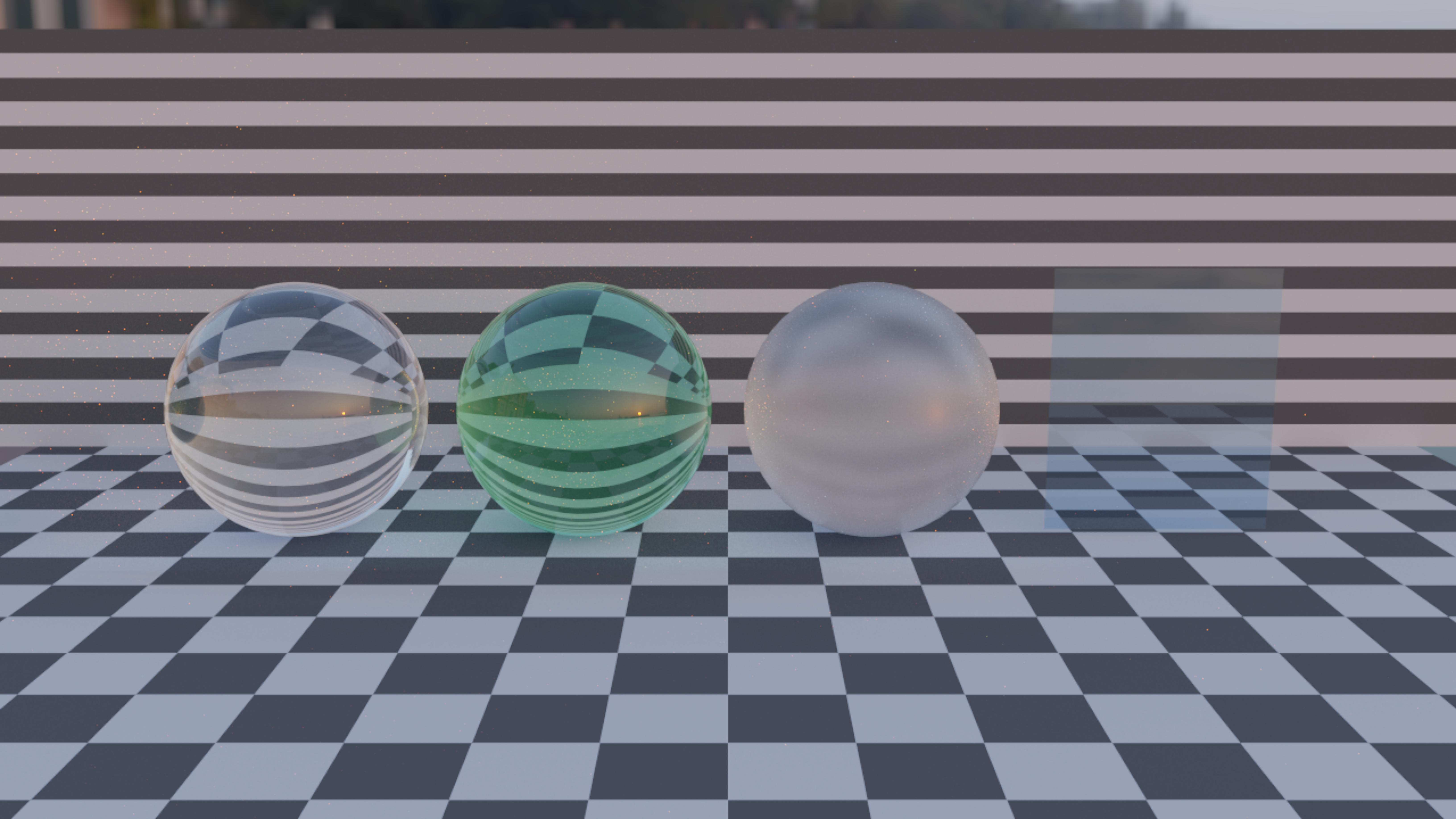
From left to right: clear glass, green absorbing glass, frosted glass and a thin
blue pane. Launch dev_docs/agents/transcripts/path_tracing_glass.yaml, or use
PathTraceGlassDemo.install(renderer, environmentPath) followed by
tracer.blitToScreen() as above. It uses ten bounces so rays can enter and leave the solids
and still illuminate another surface.
val clear = scene.material(PathTraceMaterial.glass(ior = 1.5f))
val green = scene.material(
    PathTraceMaterial.glass(
        attenuationColor = Vector3f(0.45f, 0.9f, 0.65f),
        attenuationDistance = 1f,
    ),
)
val frosted = scene.material(PathTraceMaterial.glass(roughness = 0.32f))
val pane = scene.material(
    PathTraceMaterial.thinGlass(
        ior = 1.5f,
        tint = Vector3f(0.65f, 0.85f, 1f),
    ),
)
Solid glass uses exact dielectric Fresnel reflection, Snell refraction and total
internal reflection. attenuationColor is the linear RGB fraction remaining after
attenuationDistance world units inside the solid: a red value of 0.5 becomes 0.25
after twice that distance. Components must be greater than zero and at most one;
one means no absorption. IOR must be at least one. These values are copied into
immutable material scalars when the factory is called.
Solid meshes must be closed and consistently wound outward. The built-in spheres already satisfy this. The integrator tracks one homogeneous absorbing medium; separate solids in air are supported. A camera inside one solid is inferred when its first hit is that solid’s back face. Nested or intersecting dielectric boundaries, such as water inside a glass vessel, need a medium stack and are not supported yet.
thinGlass represents an unresolved parallel pane. It transmits straight through,
combines the two interfaces' Fresnel reflections, and multiplies transmitted light
by tint once per crossing. Both faces work, and the pane does not change the
current medium. This mode is smooth only; use an actual closed slab for frosted
window glass or thickness-dependent absorption.
For solid glass, roughness above 0.001 enables single-scattering GGX reflection and transmission with matching direction PDFs and environment MIS. Very rough glass loses energy through the microfacet model's omitted multiple scattering, and how much is worth checking before you reach for a high value: a frosted slab under a unit white environment holds about 0.98 of it at roughness 0.35 and about 0.82 at 0.6. Ideal glass paths use delta-event MIS handling, and roulette accounts for refraction's radiance scaling. Each bounce still follows one stochastic ray, on either backend.
Glass requires more bounces and often more samples than opaque paint. Shadows and caustics come from traced paths; shadow rays do not shortcut solids with alpha blending. Small bright caustics therefore remain noisy, particularly under a sharp sun in an HDR map. This is optical transmission; it does not add texture alpha cutouts or transparent output-background compositing.
Accumulation and interaction
Each frame traces samplesPerFrame new paths per pixel. A 100-dimensional scrambled Sobol sequence gives
each pixel a low-discrepancy temporal sequence, with distinct Joe–Kuo direction
numbers for every sampling decision and a separate scramble per pixel/dimension. This is not a spatial blue-noise mask.
The GPU accumulates a linear HDR mean. Exposure and Reinhard tone mapping are
applied only in the display pass.
- Start with 640 × 360, one sample per frame, five bounces. Reduce resolution first when camera movement is too slow. Optional temporal reprojection helps retain convergence; there is no spatial denoiser.
- Move the supplied Field
Camerawith your usual controls. Pose and FOV changes clear history by default; withtemporalReuse, compatible pixels retain a bounded amount. Jitter and explicit lens-control edits still clear history. - Lighting, bounce count and ray epsilon changes reset history too.
reset()is an explicit reset;pausedstops sampling while leaving the current image visible. samplesreports new samples recorded since the last camera change or reset; it excludes reprojected history, whose effective weight varies per pixel.exposurechanges presentation without restarting convergence.- Size is fixed for each tracer. The fullscreen pass preserves its aspect ratio with black letterboxing when needed. Recreate the tracer to change resolution.
- Use
Backend.COMPUTE_BVHto force the portable path.Backend.RAY_QUERYrequires enabled device support and fails clearly when it is unavailable.
The integrator combines cosine-weighted diffuse and GGX reflection, environment next-event estimation, power-heuristic multiple importance sampling, and Russian roulette after the first few bounces. The environment distribution weights linear luminance by texel solid angle, accounting for the bilinear texture footprint across texel boundaries. A separately sampled 5% uniform-sphere component preserves support even for very dim texels. GGX reflection and rough transmission sample visible microfacet normals with matching PDFs. The software backend traverses a CPU-built, median-split, stackless triangle BVH.
Keeping convergence during camera motion
Enable reprojection on the existing tracer:
tracer.temporalReuse = true
tracer.temporalMaxSamples = 16 // maximum old sample weight carried across a camera move
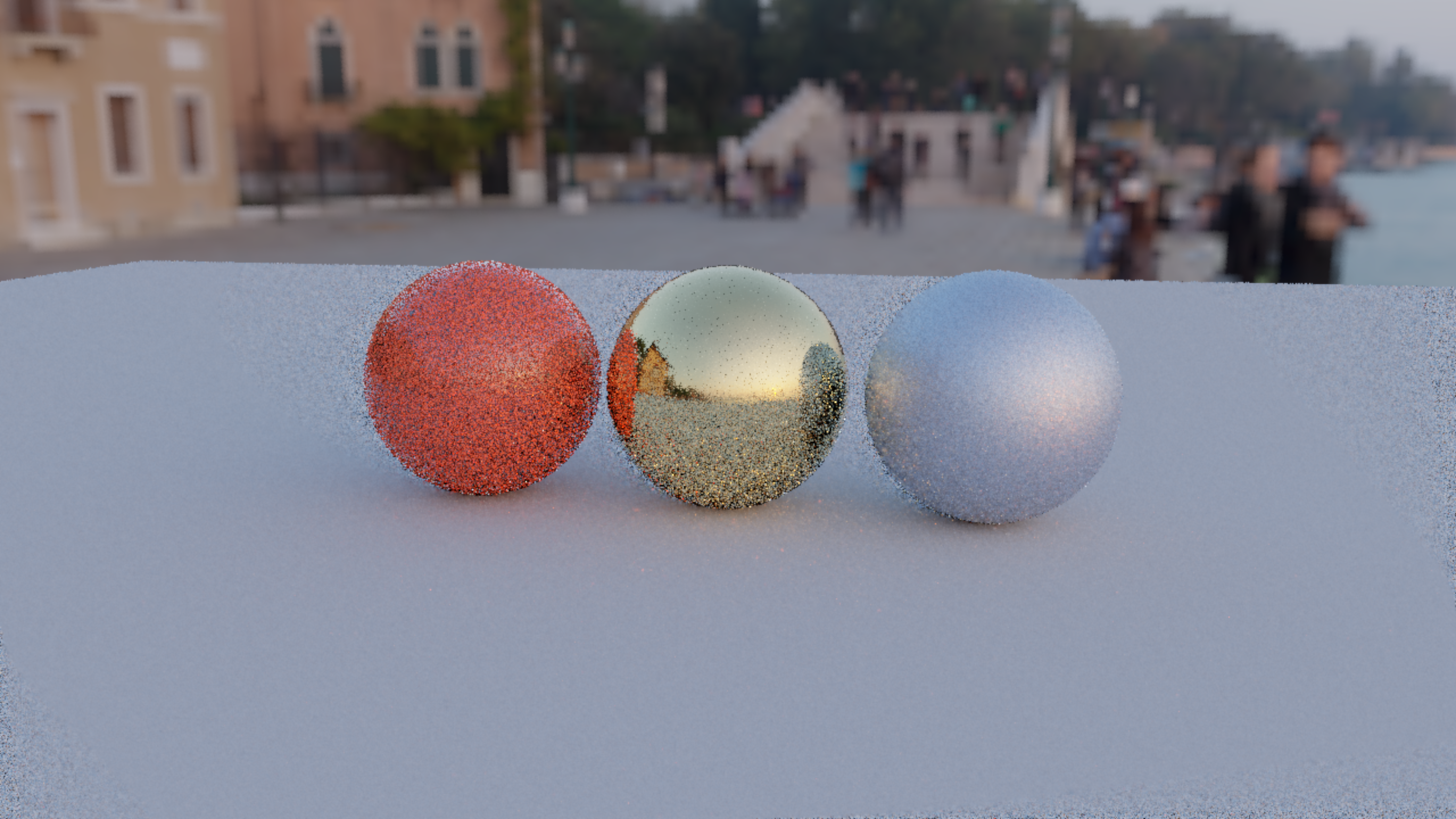
Both pictures below converge the material study to 256 samples, orbit the camera for 24 frames, and hold the last moving frame. Without reuse, every move restarts the image:
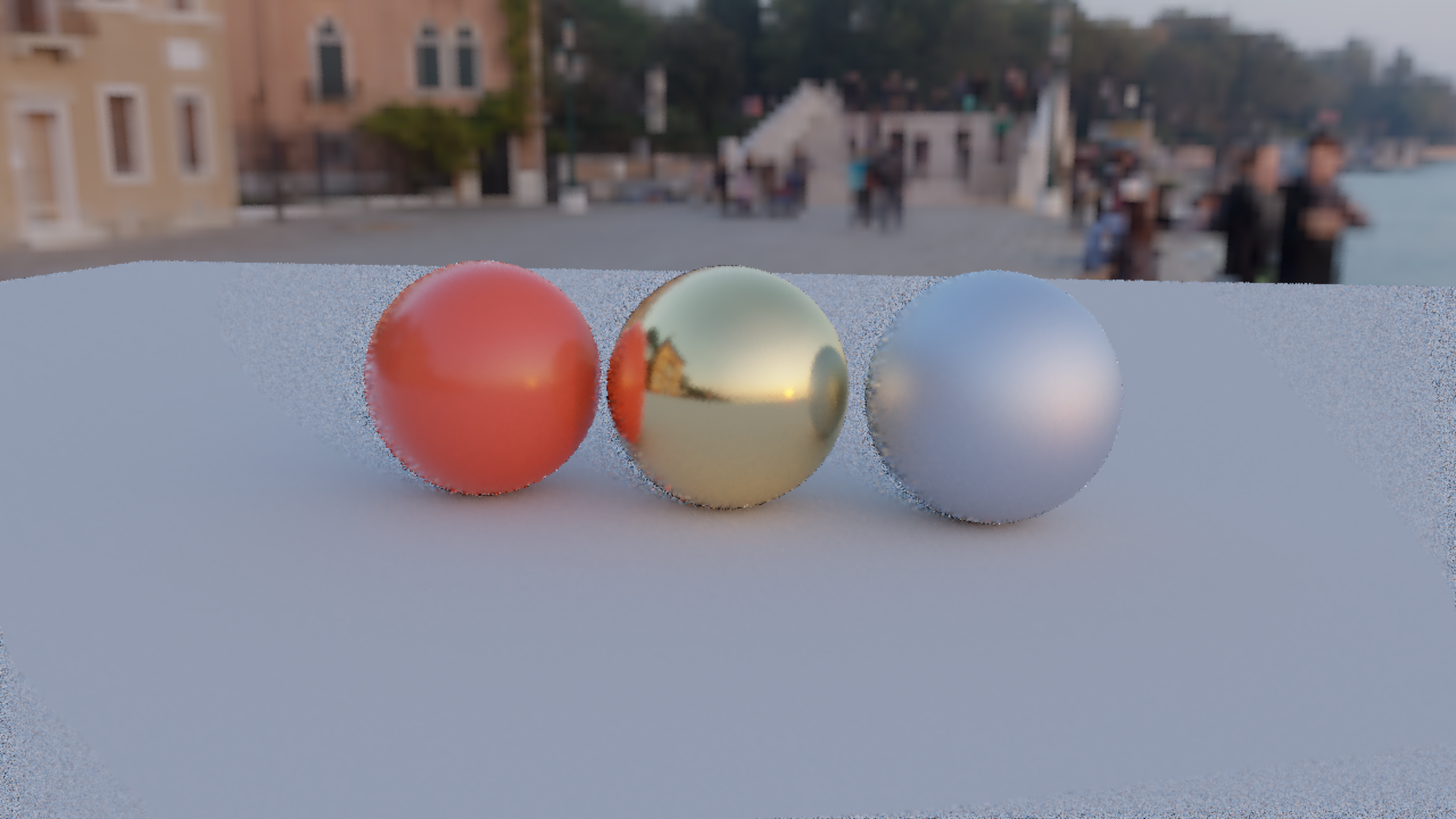
With temporalReuse = true, the rough floor and rough metal keep their history; the glossy red and gold spheres fall below the default roughness cutoff and restart:
The keyboard camera example enables this already. Each pixel stores its first hit's world position, triangle identity, normal, base colour and effective sample weight beside its linear HDR colour. On the next camera move, the tracer projects the new hit into the previous camera, gathers matching history, and combines it with fresh paths. Separate read/write history buffers avoid races between pixels. The Sobol sequence keeps advancing while you move.
History must match a nearby surface with the same material, a similar normal and
a similar base colour. It can cross triangle edges within that surface; position
checks account for the stretched pixel footprint at grazing angles while rejecting
separate layers in depth. Newly revealed surfaces and pixels outside the old view start
fresh. Alpha-tested/blended surfaces, glass and background misses start fresh on
motion too. By default, very smooth materials (roughness below 0.25) do as well.
Strong defocus has no unique
world-space correspondence: reuse is limited to surfaces whose estimated defocus
radius is at most half a pixel in both views. In-focus surfaces can therefore retain
history even with depth of field enabled.
temporalMaxSamples defaults to 16 and accepts 1..256. The actual cap is reduced
by roughness and changes in viewing direction; a large viewpoint change rejects
history altogether. Lower the cap if you see lag or smearing. Set temporalReuse = false
to return to fresh accumulation after each camera change. It is off by default because
reprojected, interpolated samples are correlated and their radiance can change with
the view: this is an approximate interactive preview, with some bias and possible blur.
With the default sensitivities, the demo's red plastic (0.22 roughness) and polished gold (0.12) fall below the
reuse cutoff, so they still restart on motion. Its rough metal (0.55) can retain
history, but with a cap of 32 its roughness-scaled maximum is about 9.7 old samples.
Increasing the cap does not override the material or visibility rejection checks;
the sensitivity controls below let you change the motion and roughness policies.
More persistence, including artifacts
For a more persistent, lower-accuracy moving image:
tracer.temporalReuse = true
tracer.temporalMaxSamples = 128
tracer.temporalMotionSensitivity = 0f
tracer.temporalRoughnessSensitivity = 0f
// Optional: permit more defocus in the history match.
tracer.temporalMaxBlurRadius = 2f
The same orbit as above with these settings. The red and gold spheres now keep history too, and their reflections are carried with the surface rather than re-traced:
| Control | Default | Effect |
|---|---|---|
temporalMotionSensitivity |
1f |
Range 0..1. Zero removes the camera-angle penalty; one applies the original conservative penalty and rejection. Intermediate values blend the two weights. |
temporalRoughnessSensitivity |
1f |
Range 0..1. Zero permits glossy surfaces and mirrors at full history weight. One applies the 0.25 roughness cutoff and roughness-squared weight. Intermediate values lower the cutoff and soften the weight reduction. |
temporalMaxBlurRadius |
0.5f |
Nonnegative defocus radius in pixels. Raise it to permit more out-of-focus surface history. |
With both sensitivities at zero, matching pixels can carry the full
temporalMaxSamples weight while moving, including on the demo's red and gold
spheres. Reflections can lag or appear attached to the surface; interpolated
history can soften or smear. Larger caps make those effects persist longer.
Restoring both sensitivities to 1f and the blur radius to 0.5f restores the
default policy.
These controls still require matching geometry, normals and material colour. Glass, alpha-tested/blended hits, background misses and newly revealed surfaces continue to start fresh. A larger blur allowance permits a match but does not guarantee one when lens samples land on different surfaces. Changing a policy control resets history once; it can then be adjusted again while the tracer runs.
When keyboard motion settles, the controller leaves the camera unchanged, including
near-vertical views. Pixels then accumulate fresh paths normally; the motion cap no
longer applies, and the retained history's influence diminishes as new samples arrive.
Lighting, shader reloads, explicit focus/aperture/jitter edits, reuse-setting changes
and tracer.reset() discard history. Animated material parameters still need an
explicit reset. Scene geometry remains a static snapshot; object motion vectors and
a spatial denoiser are not part of this implementation.
The two history buffers are allocated on first use and retained until the tracer
closes. They add 128 bytes per pixel: about 28 MiB at 640 × 360, or 253 MiB at
1920 × 1080. samples continues to count fresh samples for the current view, so it
may stay at samplesPerFrame while moving even though valid pixels carry history.
A GPU regression covers this: retained weights and noise reduction under a small
translation, then continuous translation, rotation, FOV changes, disocclusion, camera
cuts, transparent backgrounds, lens invalidation, and jitter crossing triangle seams
on a densely tessellated plane. What it measures and at what size is in
dev_docs/PATH_TRACING_MEASUREMENTS.md. Note that the noise reduction it reports
includes interpolated history, so it is not a count of independent samples and not a
general speedup.
Reducing bright specks
Small bright sources in an HDR map can produce occasional bright pixels, often called fireflies. They can take many samples to fade, especially in reflections and caustics. More samples reduce ordinary noise; they do not guarantee a clean preview at an interactive sample budget.
For stubborn specks, an optional filter limits the indirect luminance of each path sample before accumulation:
tracer.indirectClamp = 10f // linear HDR luminance; 0f disables (the default)The clamp scales RGB together to preserve hue. It leaves the camera background, visible emission, first reflections and first-surface environment lighting untouched. It limits the summed contribution from subsequent surface interactions, including light transmitted through multiple glass interfaces. This is a biased filter: lower limits suppress specks more strongly but can dim indirect lighting and caustics. The threshold is in scene units, before exposure; changing it resets accumulation. The sampling improvements work with the clamp disabled.
Start at 10f for the bundled sunset scene. Lower the limit if specks are still
obtrusive; raise it if reflected or transmitted light becomes too dim. Set it to
0f when preserving the unclamped lighting matters more than fast convergence.
With temporal reuse disabled, use tracer.samples to compare views at the same sample count, and adjust
tracer.exposure separately for display brightness.
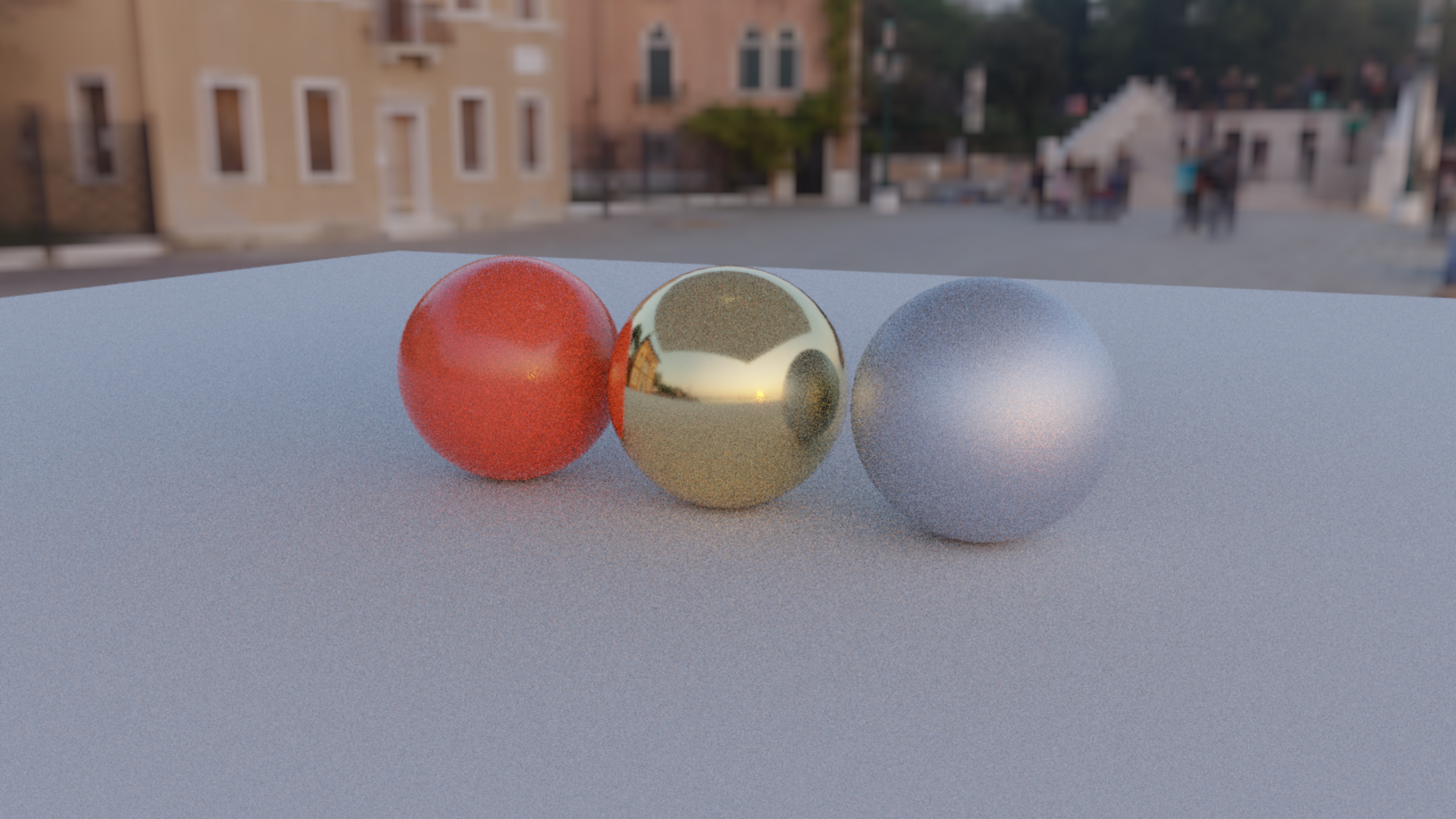
The clamp is easiest to see on light that paths find only by chance after a bounce. Here
the material study has a ceiling just out of frame and, under it, a lamp the size of a coin
that shines only upward, with emitterSampling off. The floor and spheres are lit by the
patch of ceiling the lamp brightens, and a path finds that light only when its second bounce
happens to hit the lamp. After 16 samples per pixel with the clamp off, those rare hits are
the specks:
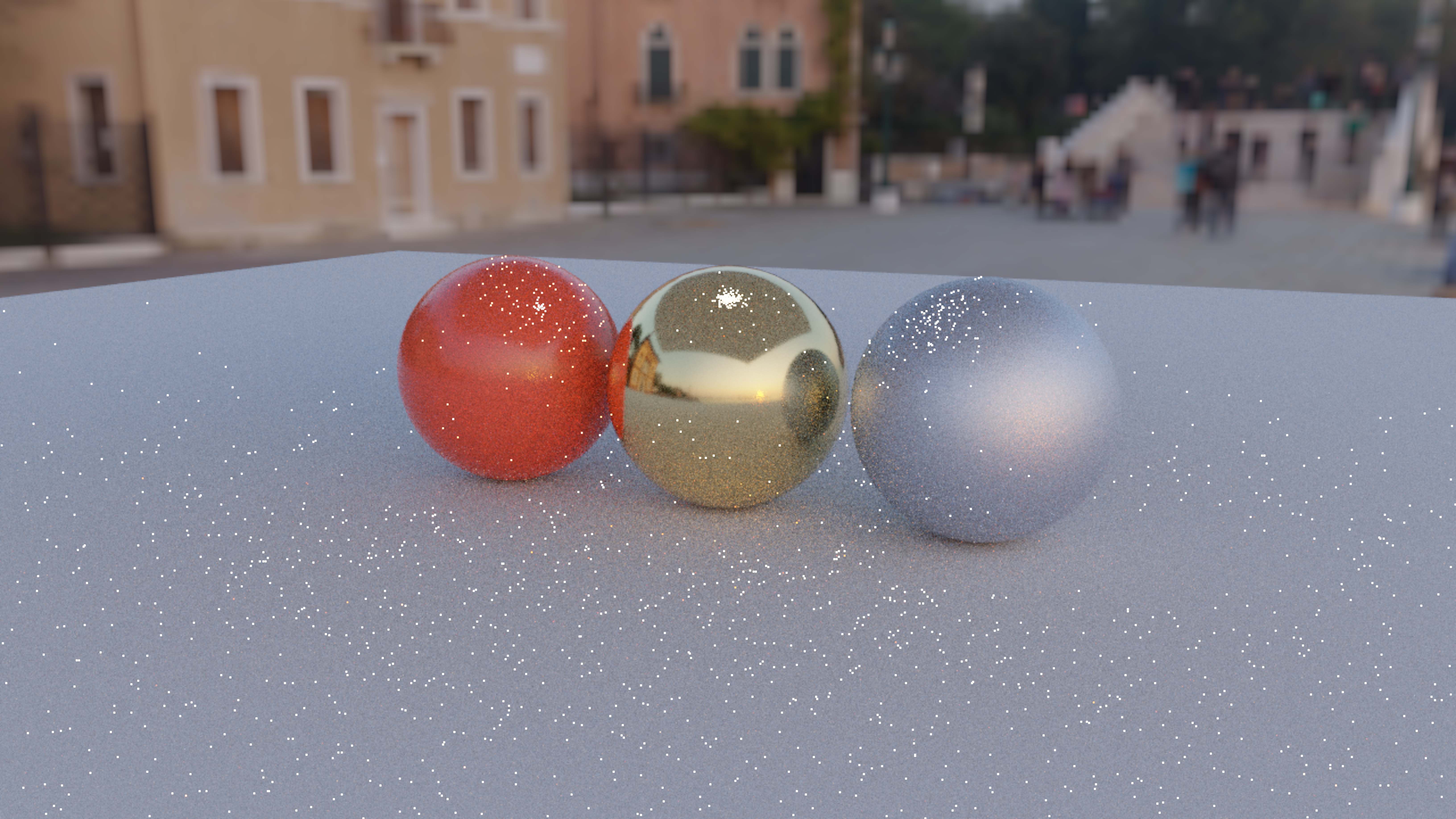
With indirectClamp = 1f, each of those samples is capped at a luminance of 1 before it
is averaged in. The specks go, and with them most of the light the lamp sends by way of
the ceiling: that light is carried by exactly those rare samples, which is the bias the
clamp trades for a clean image.
Sampling the lamps directly
The clamp above gives a clean preview at the cost of some bias. Sampling small, bright emissive triangles directly can reduce those specks without adding bias. Without it, a path finds a lamp only by scattering into it by chance; the smaller and brighter the lamp, the rarer and spikier those hits. With it, emissive triangles are importance-sampled from a cumulative table and connected with a shadow ray, as the environment map is. It is on by default:
tracer.emitterSampling = true // the default; false finds lamps by BSDF sampling only
println("${tracer.emitterCount} emissive triangles are sampled directly")
A table over the scene's emissive triangles is built on the CPU and uploaded beside the environment's, weighted by emitted power: triangle area times emitted luminance, doubled when both faces radiate. At every non-delta surface interaction the integrator sends a second shadow ray, toward a point sampled uniformly over a triangle drawn from that table, and weights the result against what a BSDF sample would have been worth in the same direction. The emission a BSDF sample does find carries the reciprocal weight. The two strategies therefore compose instead of double-counting, and the result is the same image, reached sooner.
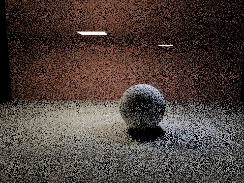
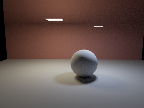
Both of these are 256 samples per pixel at 480 × 360, three bounces, two lamps of 0.64 and 0.12 square units in a black environment. They are one flag apart:
How much emitter sampling helps on this scene
PathTraceEmitterGpuSmoke measures the difference on real GPU readback. Over
the 6,746 lit pixels of a 96 × 72 render of the same scene — luminance between 0.004
and 6, which excludes the black background and the directly visible lamps — at an
equal 257 samples per pixel:
| Emitter sampling | RMSE against a 65,536-sample reference | Ratio |
|---|---|---|
| off | 0.13534 | |
| on | 0.00389 | 34.8× |
The ratio depends on the scene: a larger lamp, or any environment light, lowers it. The check asserts a floor of 28×.
Both converge to the same image. That is checked against the environment path: a sphere inside a
uniformly emissive cube, at one bounce, is the identical integral as the same sphere
under a constant unit environment map, and the two agree to within a pixel-level
residual that shrinks as the reference budget grows. The agreement figures are in
dev_docs/PATH_TRACING_MEASUREMENTS.md.
The extra shadow ray costs one traversal per surface interaction. A scene with no emissive triangle is bit-for-bit identical with the control on or off.
Each emissive triangle is weighted by its area times its emitted brightness: the emission factor, times the mean of its emission texture when it has one. Three things are excluded from the table, and in each case the consequence is that emission from them is found by BSDF sampling alone, exactly as before:
- Emitters behind stochastic alpha coverage (
AlphaMode.MASKorBLEND). The two strategies would otherwise disagree about whether the emitter is there at all. - Emissive glass. Transmissive materials are shaded on the dielectric path.
- Zero-area triangles, which cannot be sampled by area at all.
maxBounces is a path length limit, and a shadow ray reaches one segment past it: the connection from the
last path vertex to a light is a scattering event that a BSDF hit would have needed
another bounce to make. So emitterSampling = true at three bounces transports what
false transports at four. That is more light for the same budget, not a brightness
bug — but a strict A/B of the two flags at equal maxBounces shows the deeper
setting slightly brighter, and on this scene that difference is 1.9% of the image.
Current limits
This is a basic static-scene renderer. It does not yet include heterogeneous scattering volumes, nested dielectric media, deformation/refitting, motion blur, spatial denoising or an OpenXR stereo pass. Emissive triangles are importance-sampled by area and power (see above), but there is no spatial or directional light hierarchy, so a scene with thousands of small lamps still spends most of its shadow rays on lamps that cannot reach the shading point. The intended interactive resolution is a workload choice, not a frame-rate guarantee.
Getting pixels back out
You can run the GPU checks against your own machine — they cover readback colours, material
placement, image orientation, accumulation resets, white-furnace energy, glTF textures and
transforms, the glass models, and the clamp. dev_docs/PATH_TRACING_MEASUREMENTS.md says what each
one covers. The standalone RayTracingGpuAudit also runs camera, temporal, fog and ray-pipeline
checks; --all adds the statistical emitter/medium suites and a GPU timing sweep. Its report
records the actual device and enabled backends. From a launched renderer child:
val r = renderer
val verify: suspend () -> Unit = { PathTraceGpuSmoke.run(r) }
start(verify)
tracer.readLinear() returns the actual GPU RGBA accumulation buffer as floats;
alpha holds primary visibility coverage. RGB is premultiplied by alpha; samples
reports the sample count. Glass hits have coverage one, including their traced
refraction; this alpha is not a transmission matte. Call it outside frame recording on Field's render thread.
It waits for GPU readback and is intended for export and checks, not the frame loop.
Create/install/close on that same thread, as with other Field 4 resources.
close() detaches the passes immediately and defers destruction until in-flight
frames have retired.
The reflection model follows the standard GGX microfacet formulation. The glass model follows the dielectric BSDF formulation. The optional traversal uses the Khronos ray-query interface.
What a frame costs
On an RTX 4090 with Vulkan ray queries, the three-sphere scene takes 1.44 ms at 1280 × 720, one sample per frame and five bounces. On the same GPU, the software BVH path takes 14.09 ms. These are GPU tracing times; scene construction, readback and presentation are outside the interval.
| Resolution | Samples/frame | Ray query median / p95 | Software BVH median / p95 |
|---|---|---|---|
| 640 × 360 | 1 | 0.344 / 0.368 ms | 6.253 / 6.620 ms |
| 640 × 360 | 4 | 1.584 / 1.637 ms | 18.029 / 20.957 ms |
| 1280 × 720 | 1 | 1.444 / 1.499 ms | 14.094 / 14.508 ms |
| 1280 × 720 | 4 | 4.979 / 5.159 ms | 19.342 / 19.881 ms |
Measured on Linux, NVIDIA 610.43.02, 24 September 2026: 6,626 triangles, a unit environment,
32 warm-up frames and 256 measured dispatches per setting, without denoising. AUTO
selects RAY_QUERY when its required features are enabled; the tracer's live summary
reports which backend it actually selected. More geometry, glass and longer paths change
the cost, so measure your own scene before choosing its sample budget.
For comparison, earlier Apple M1 Max / MoltenVK measurements at 640 × 360 and one sample per frame were about 4.3 ms for the opaque scene and 10 ms for the ten-bounce glass study. Those are different hardware and traversal paths, not a like-for-like GPU comparison.
indirectClamp = 10f is the cheapest thing you can do about caustic specks. On the sunset material
study it took a patch from twenty strong specks to none, for about 0.14% off the patch's mean
radiance — bias you can measure but not see. Sampling improvements alone do not remove those
outliers, which is why the clamp exists.
dev_docs/PATH_TRACING_MEASUREMENTS.md has the per-setting speck counts, the white-furnace and
slab-transmission agreement, and the sample counts and warmup behind the two timings.
Reading a running tracer
print(tracer.h), or letting a box's output be the tracer itself, gives a nine-row
summary of what it is doing:
PathTracingRenderer 'path-tracer'  COMPUTE_BVH · software BVH traversal

image        640×360 · 6626 triangles
samples      950 spp in generation 2 · 112.4 spp/s
last reset   integrator reloaded
camera       (3.5, 2.4, 7.5) → (0, 0.65, 0) d=8.459
up           declared (0, 1, 0) ≠ effective (-0.087, 0.978, -0.187) (11.94° apart)
paths        5 bounces · 1 spp/frame · jitter 1
recorded     950 points over 8.5 s · 0 resets

21 tuning properties, the camera basis and the convergence log are in .h2
Rows at their default are dropped rather than shown as zeros, so a plain tracer is five rows and each of the five optional groups — a non-agreeing up, a lens, temporal reuse, fog, an attached convergence log — adds one. Ten is the ceiling.
up is the part of camera.up perpendicular to the view direction, normalised: the
same up the raster camera's lookAt builds its image with. A camera that looks up or down
with the default up of (0, 1, 0), as the material study's does, has an effective up that
differs from the declared one, here by 11.94°, and the row says by how much. Both renderers
use the effective up, so their images agree. The row appears only when the two differ.
samples counts within a generation, and resetGeneration counts the generations.
Two sample counts are comparable only if the generation between them has not advanced;
lastResetReason says what ended the previous one — property edit, camera motion,
focus or lens edit, Sobol sequence exhausted, shader reloaded, integrator
reloaded or first frame.
tracer.h2 is the drill-down: the same values grouped into image, convergence,
camera, tuning and objects rather than flat, with the derived camera basis beside
them and the renderer, camera, output and materialModule sub-objects still
expandable onto their own renderings.
Recording convergence
val log = tracer.recordConvergence()
// … later, from any box that can see the tracer
showConvergence(log)
The tracer appends (wall time, samples) to an attached log from inside its own render,
so recording costs no frames and sees resets that sampling samples at frame boundaries
would miss — a camera being dragged resets accumulation on every frame it moves.
showConvergence is one call to showSignals, so it is the ordinary dark-mode Plotly line
plot: samples against wall seconds, with a full-height dashed rule at each reset carrying
its reason into the legend. Consecutive resets with the same reason collapse to the first
of the run, or a ten-second camera drag would contribute six hundred identical rules.
Memory is bounded. At maxPoints the log drops every other point and doubles its sampling
stride, so a run of any length keeps the shape of its curve in fixed memory at halving
resolution. points is what is retained, framesPerPoint is the current stride.
Replacing the integrator on a running tracer
pathTracingHere above puts the material function in a box's editable compute
property. To replace the integrator — trace.comp itself — on a tracer that is
already rendering:
// The packaged integrator, with this device's HARDWARE_QUERY define already applied.
val directOnly = tracer.integratorSource().replace("return vec4(radiance+indirect,1);", "return vec4(radiance,1);")

println(tracer.reloadIntegrator(directOnly))

// integrator reloaded (30326 chars); accumulation restarts, camera and scene preserved
The material study at the top of this page, after the swap:
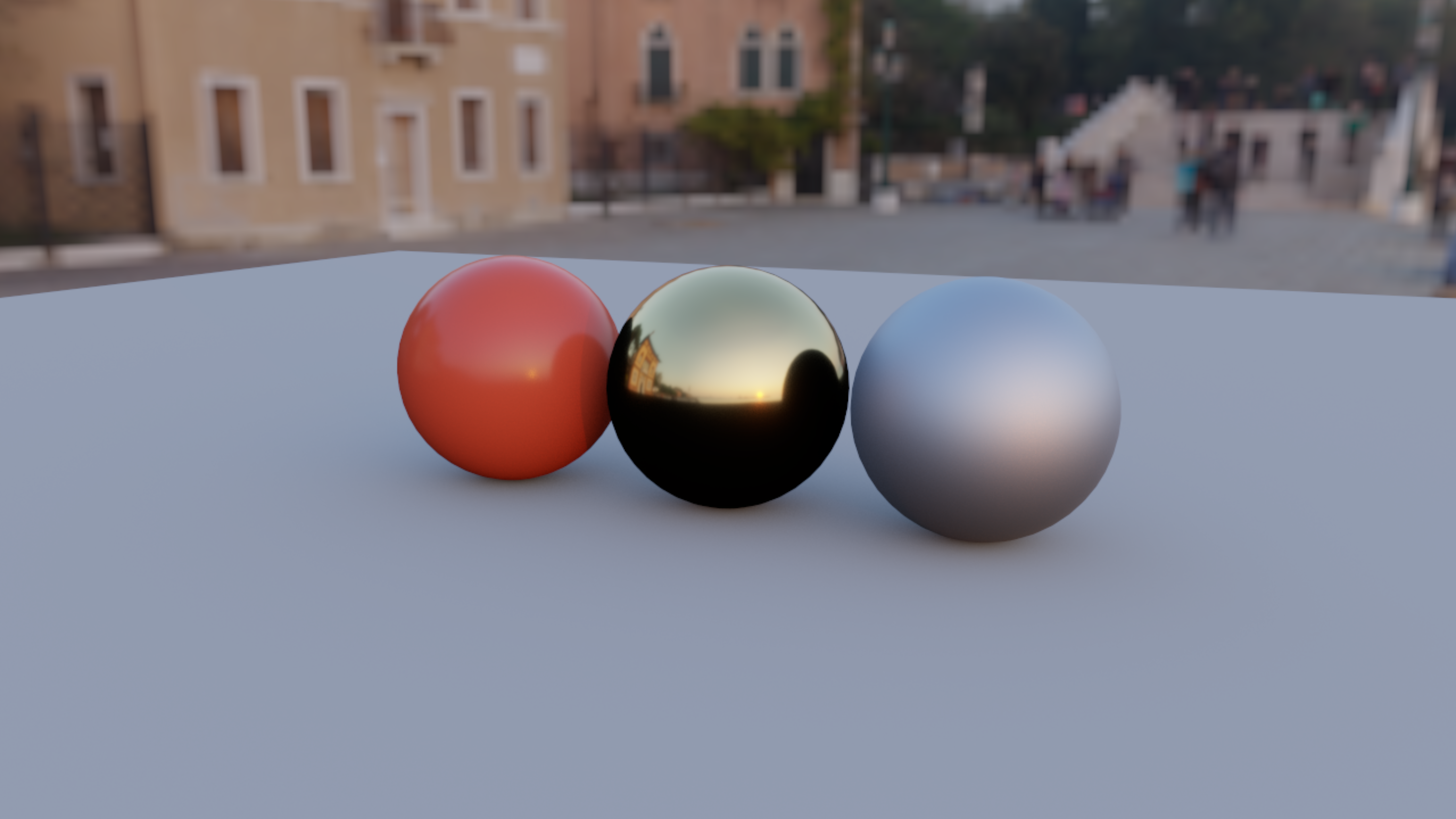
The scene, the environment, the accumulation buffers, the camera pose and every tuning
property survive; only the compute pipeline is rebuilt. Swapping the material study to
direct-light-only changes most of its pixels and leaves camera.at, camera.target and
camera.up bitwise identical — the measured version of that swap is in
dev_docs/PATH_TRACING_MEASUREMENTS.md.
integratorSource(file) takes the source from disk instead, which is what you want while
editing src/jvmMain/resources/afield/four/pathtracing/trace.comp — the packaged resource
will not reflect your edit until the next build. Either way the backend's #define
HARDWARE_QUERY is applied for you, and applied idempotently: source that already carries
one, or lacks one, both come out right for this device.
reloadIntegrator reports one of three outcomes, as ComputeModulePointer.reloadOutcome does for
any compute module.
IntegratorReload.status |
meaning | ok |
reloaded |
|---|---|---|---|
UNCHANGED |
byte-identical to the live pipeline. Nothing rebuilt, nothing reset | true |
false |
RELOADED |
a new pipeline is live, the superseded one is queued for release, accumulation restarts | true |
true |
FAILED |
it did not compile. The last working pipeline is still rendering; errors carries the compiler's messages |
false |
false |
A failed reload is invisible in the window — the image carries on from where it was — which is the same guarantee the material-shader path gives.
A successful reload sets samples back to 0 at once, so waiting on a sample count afterwards waits
for the new integrator's samples.
The opaque path tracer can also feed Ray Reconstruction, with raw and progressive views retained.