Graphics on the GPU
The "4" in Field·4 is its Vulkan renderer, driven from boxes. Write a few lines of Kotlin, launch the box, and you can change the picture while it runs. You'll also write shaders in box properties; the result usually appears in a native window, though you can draw into an output panel too.
For the native window you'll need a working Vulkan driver and a desktop session. Welcome's Vulkan panel can check the machine; installation has platform details. If you haven't connected boxes yet, Connecting Boxes shows the gesture used below. The first graphics starting point is a shorter way to open a window and draw a triangle.
A renderer, and a box beneath it
One box opens the window and runs the frame loop. Its code publishes the window and the renderer as properties, builds them once, and starts the renderer:
prop<Window>(window)
prop<Renderer>(renderer)

once.renderer {
    window = Window("Field")
    Renderer(window)
}

start(renderer::run)
once.renderer { } keeps the renderer across re-runs, so running this box again does not open a
second window. Every box you connect beneath it (select the renderer box, then the new box, and
press g) can use renderer directly, the same way a child box sees any property its parent
publishes. The canonical_graphics starting point (Welcome → Starting points →
canonical_graphics) already has this box, named window; launch it first.
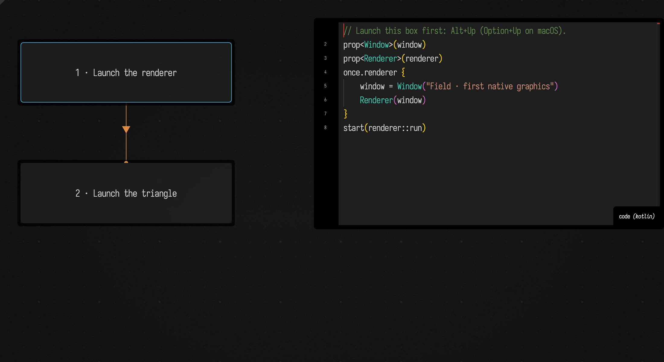
The first-graphics starting point from First steps
is this pair: the renderer box with its code open on the right, and the box beneath it, joined by the
arrow g draws.
A shader-driven result
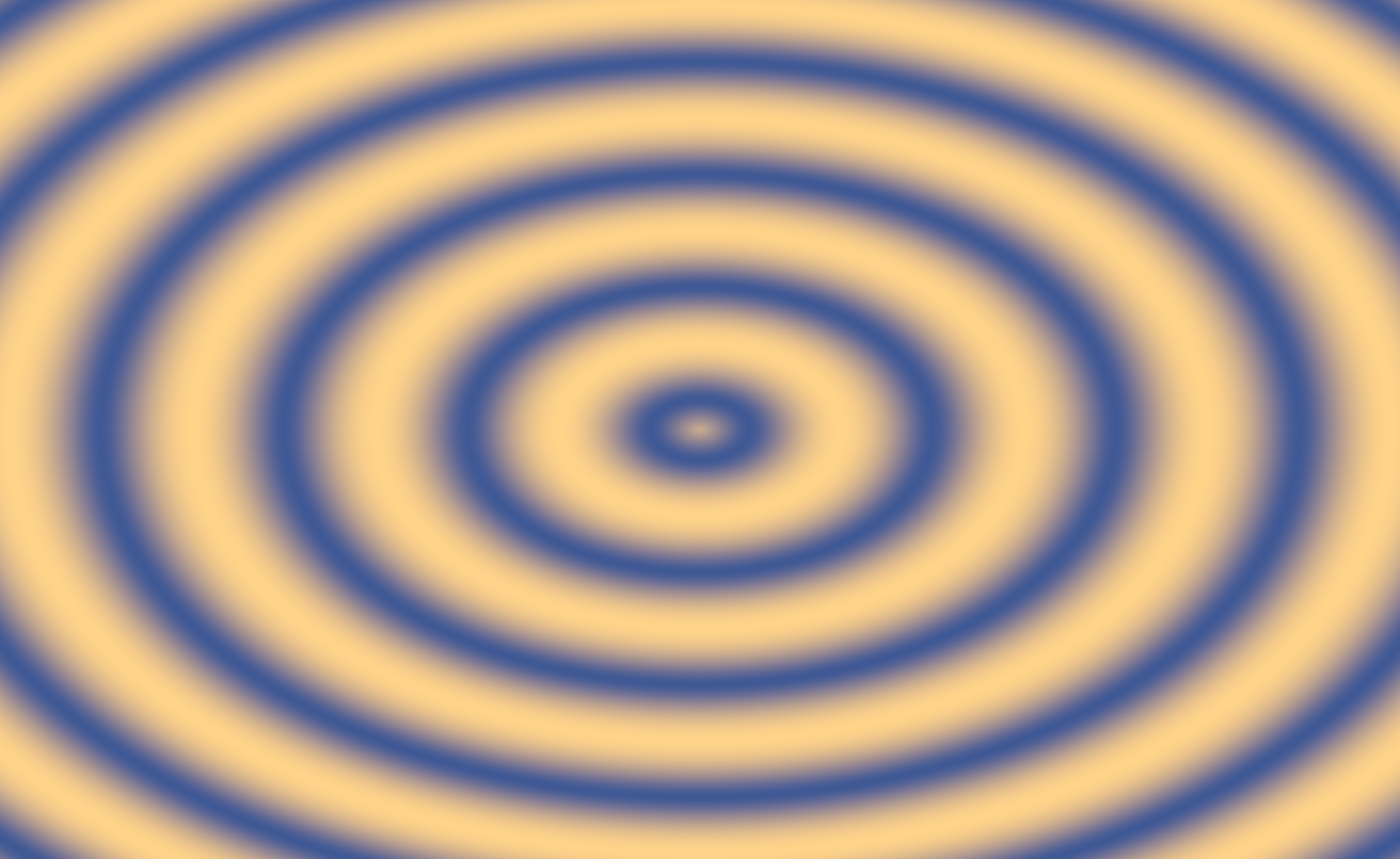
This box draws one square that covers the window, and lets its fragment shader decide every pixel.
The box has three properties: code (the Kotlin below), and vertex and fragment, the two
shaders.
val started = AnimationClock.nowSeconds()

renderer += moduleHere {
    +Mesh("square") {
        // four corners in clip space, where the window runs from -1 to 1, and two triangles spanning the corners
        set(4, 2) {
            pos.add(-1, -1, 0, 1, -1, 0, 1, 1, 0, -1, 1, 0)
            tc.add(0, 0, 1, 0, 1, 1, 0, 1)
            tri.add(0, 1, 2)
            tri.add(0, 2, 3)
        }
        // read once per frame, and handed to the shader as `pc.time`
        time = { AnimationClock.nowSeconds() - started }
    }
}
moduleHere { } makes a draw pipeline from this box's vertex and fragment properties, and
renderer += ... puts it on screen. The names inside set(4, 2) { } are not part of a library:
pos and tc exist because the vertex shader declares those two inputs, and tri is the index
buffer every mesh has. Here is the vertex shader, the box's vertex property:
#version 450
layout (location = 0) in vec3 pos;
layout (location = 1) in vec2 tc;

layout (location = 1) out vec2 ftc;

void main()
{
    gl_Position = vec4(pos, 1);
    ftc = tc;
}
time comes from the fragment shader, shown below, the same way. It is a member of the shader's
push constants, the small block of values the CPU hands the shader fresh each frame, so the mesh gets a time property, and the function assigned to it is called every frame: here,
seconds since the box ran. The shader declares a float, and Field narrows the Double to it as it
writes the value. The clock is the AnimationClock from
Frames and the Animation Loop, so the rings drift outward at the same rate live and in a recording.
#version 450
layout(location = 0) out vec4 uFragColor;
layout(location = 1) in vec2 ftc;

layout(push_constant) uniform constants {
    float time;
} pc;

void main()
{
    vec2 p = ftc * 2.0 - 1.0;
    float r = length(p);
    float rings = 0.5 + 0.5 * sin(24.0 * r - 3.0 * pc.time);
    vec3 col = mix(vec3(0.05, 0.10, 0.30), vec3(1.0, 0.65, 0.25), rings);
    uFragColor = vec4(col, 1.0);
}
A live edit
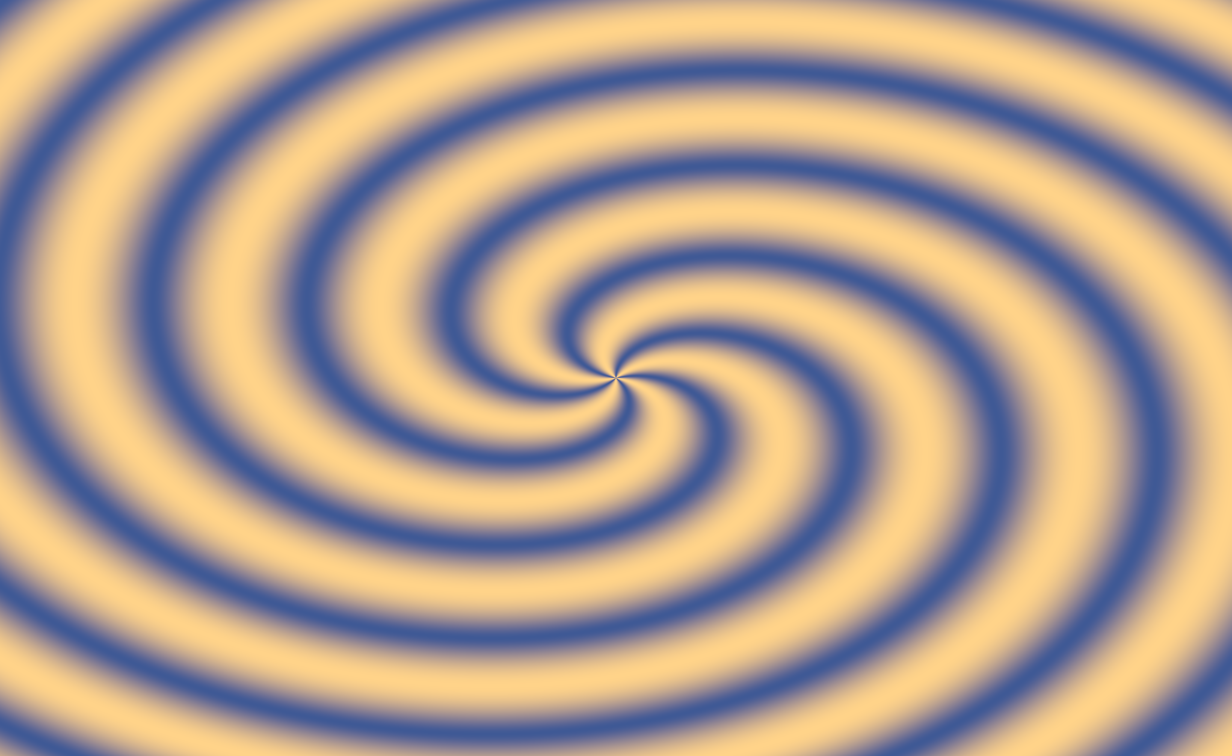
Shaders are properties like any other, and editing one is a live edit. Open the box's fragment
property and add the angle around the centre to the line that makes the rings:
float rings = 0.5 + 0.5 * sin(24.0 * r - 3.0 * pc.time + 5.0 * atan(p.y, p.x));Press Alt-Enter in the GLSL editor and the rings become a five-armed spiral, still turning. You do
not need to run the box again: Field recompiles the shader in place, the window stays open, and
the renderer keeps its frame loop.
Geometry and a camera
The square was drawn straight into the window's own coordinates. Geometry you want to look at from
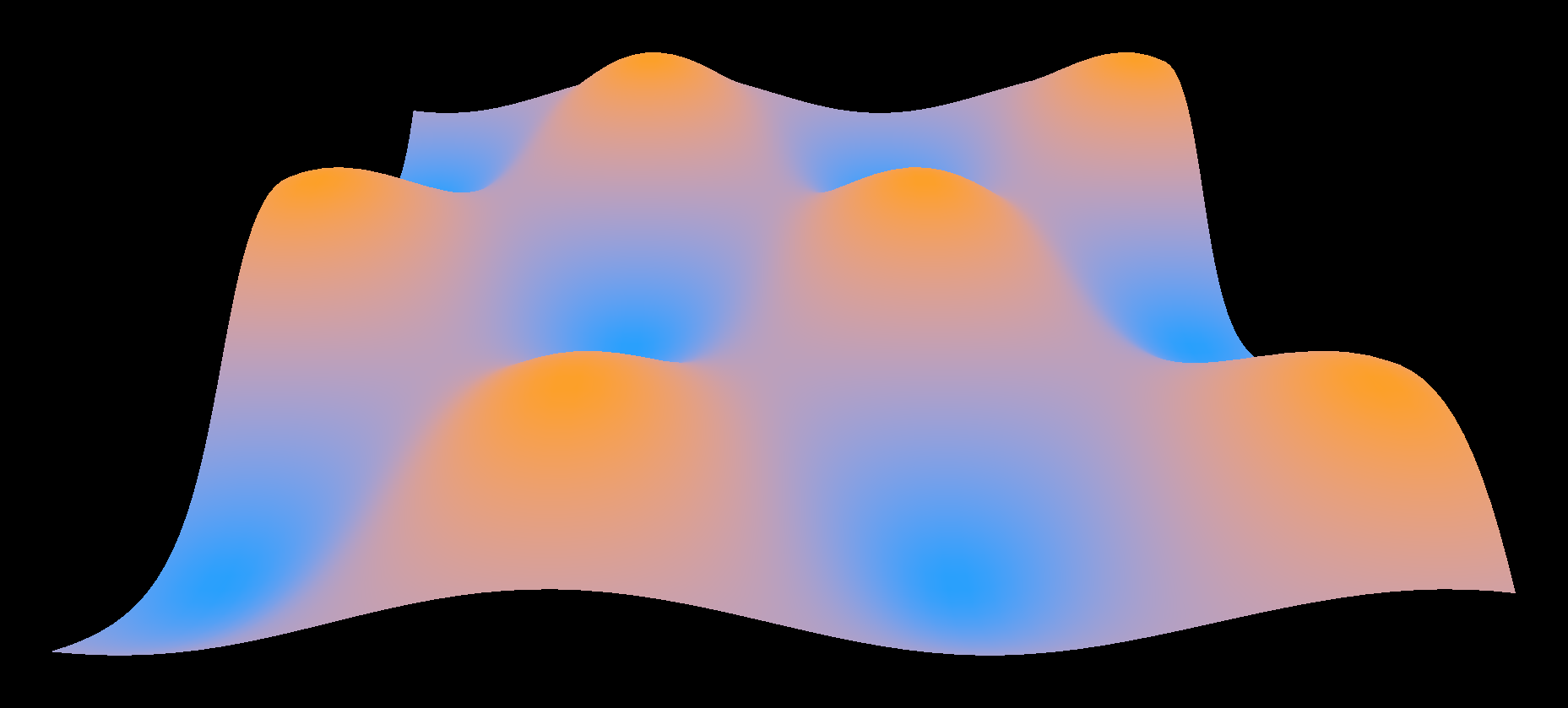
somewhere goes through a Camera instead. This box builds a 60 × 60 grid of vertices, lifts each
one by a wave, colours it by its height, and joins neighbours into triangles:
val camera = Camera()
camera.at = vec(0, 5, 9)

val n = 60

renderer += moduleHere {
    +Mesh("surface") {
        // the projection and view matrices, read by the vertex shader as `pc.p` and `pc.m`
        p = camera.p
        m = camera.m

        set(n * n, 2 * (n - 1) * (n - 1)) {
            for (j in 0 until n) for (i in 0 until n) {
                val x = (i / (n - 1.0) - 0.5) * 8
                val z = (j / (n - 1.0) - 0.5) * 8
                val y = 0.8 * Math.sin(1.3 * x) * Math.cos(1.1 * z)
                val h = 0.5 + 0.6 * y
                pos.add(x, y, z)
                col.add(h, 0.35, 1 - h, 1)
            }
            // two triangles for each square of the grid
            for (j in 0 until n - 1) for (i in 0 until n - 1) {
                val a = j * n + i
                tri.add(a, a + 1, a + n)
                tri.add(a + 1, a + n + 1, a + n)
            }
        }
    }
}
The vertex shader now declares a colour input as well as a position, so the mesh has col beside
pos. It also takes the camera's two matrices as push constants, giving the mesh p and m:
#version 450
layout (location = 0) in vec3 pos;
layout (location = 1) in vec4 col;
layout (location = 0) out vec4 fcol;

layout(push_constant) uniform matrices {
    mat4 p;
    mat4 m;
} pc;

void main()
{
    gl_Position = pc.p * pc.m * vec4(pos, 1);
    fcol = col;
}
Move camera.at and run the box again to look from somewhere else. Change the wave, or n, and the
surface is rebuilt.
Drawing into the box itself
In Field's desktop app a renderer can also draw into a box's output panel, so the live picture sits
next to its code instead of in a separate window. An ElectronRTTView is that picture: a 640 × 360
image the renderer draws into each frame, streamed to the panel. Give it the module from before, and
the spiral turns inside the box:
import afield.media.stream.ElectronRTTView

val view = ElectronRTTView(640, 360)
val started = AnimationClock.nowSeconds()

view +=
    "content" to
        moduleHere {
            +view
            +Mesh("square") {
                set(4, 2) {
                    pos.add(-1, -1, 0, 1, -1, 0, 1, 1, 0, -1, 1, 0)
                    tc.add(0, 0, 1, 0, 1, 1, 0, 1)
                    tri.add(0, 1, 2)
                    tri.add(0, 2, 3)
                }
                time = { AnimationClock.nowSeconds() - started }
            }
        }

display("main", view.html())
+view inside moduleHere { } sends the module's drawing into the view instead of the window,
view += ... attaches the module to it, and display puts the view in the box's main output.
A web browser, including Field's HTTP mirror, shows a message in place of the frames.
Where to go from here
- Field 4 Graphics is the full walkthrough: buffers, cameras, compute shaders and particles, textures, glTF, render-to-texture and blur, each with its picture.
- canonical_graphics is that walkthrough's document: one box per lesson, each with its code, its shaders and the picture its window drew. Open Welcome → Starting points → canonical_graphics in Field to run them.
- Graphics in an Output Area has more on the view in the panel: sizes, re-running, sharing it between boxes, and Linux.
Next on the Tour, Looking at Data starts with values you can inspect in a box and works up to a live GPU probe.