From modules to reconstruction
Start with a moduleHere() module drawing into a RenderToTexture, and give it the depth and
motion images reconstruction needs for history. Then record DLAA or Super Resolution after the
source pass. Ray Reconstruction extends the graph with raw lighting and material guides.
Open the reconstruction_plumbing starting point for the complete DLAA/SR wiring, or rr_plumbing for the RTXDI/RR version. Both put the scheduling in the editable Kotlin box and the attachment writes in its vertex and fragment properties. Run the renderer box, then the scene box. The Neural reconstruction and Ray reconstruction pages have starting points with more controls for comparing modes.
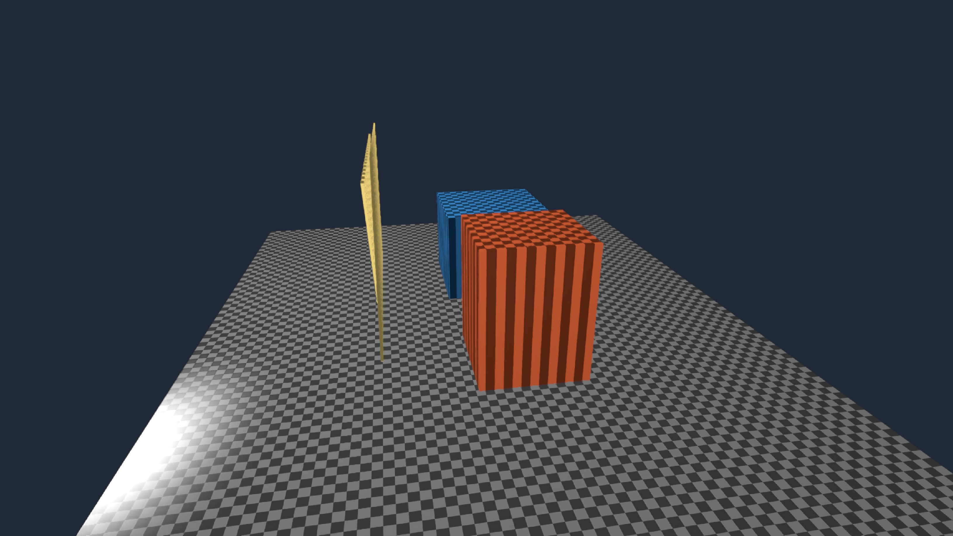
The graph you are building
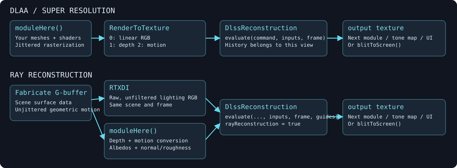
For DLAA and SR, the order is:
Meshes + moduleHere() → source render target [RGB, depth, motion] → DlssReconstruction.evaluate() → output texture → display or another module.
For RR, it becomes:
Fabricate G-buffer → raw RTXDI lighting + guide-conversion moduleHere() → evaluate(..., guides) → output texture → display or another module.
These are GPU passes in Field's existing command stream. The native NGX adapter receives Vulkan image handles; there is no CPU image readback between them. A texture binding makes an image accessible to a shader. It does not schedule the module that produces it. The explicit render calls below are what establish that order.
First choose the two sizes
The output size is the image you want to display. Query the SDK before allocating the smaller source:
val outputSize = ReconstructionSize(1920, 1080)
val mode = ReconstructionMode.QUALITY
val inputSize = DlssReconstruction.recommend(renderer, outputSize, mode).optimal
val neural = DlssReconstruction(renderer, inputSize, outputSize, mode)
DLAA uses native resolution. QUALITY, PERFORMANCE and ULTRA_PERFORMANCE choose supported smaller inputs. On the machine that built these docs, the recommended inputs for 1080p were 1280 × 720, 960 × 540 and 640 × 360. Query your runtime instead of encoding those numbers into the renderer.
In reconstruction_plumbing, change mode at the top of the box and rerun it to recreate the resources. Its Bypass reconstruction control shows the same source-sized render, enlarged for display. This is useful for seeing what information SR receives; it is different from the native-resolution Source comparison on the Neural reconstruction page. Without NGX, this starting point allocates a native-resolution source and shows it with a diagnostic.
Write a small G-buffer from moduleHere()
A single raster module can write several attachments at once:
val source = RenderToTexture(renderer) {
    width = inputSize.width
    height = inputSize.height
    useDepth = true
    colorAttachments = 3
    colorFormats = [
        VK_FORMAT_R16G16B16A16_SFLOAT, // opaque linear HDR color
        VK_FORMAT_R32_SFLOAT, // sampled projected depth
        VK_FORMAT_R32G32_SFLOAT, // current → previous motion, input pixels
    ]
}
val sceneModule = moduleHere {
    +source
    depthTest = true
    depthWrite = true
    blend = false
}
source += "scene" to sceneModule

// Add your meshes to sceneModule as usual.
renderer is inherited from the parent renderer box. +source configures the module's attachments and render pass. The corresponding fragment outputs are:
layout(location=0) out vec4 color;
layout(location=1) out float depth;
layout(location=2) out vec2 motion;
Drawn side by side, the three colour attachments of one frame are the lit colour, the depth guide (shown here as red, brighter when nearer, background black) and the motion vectors (red and green for the horizontal and vertical motion, offset so that zero motion is olive):
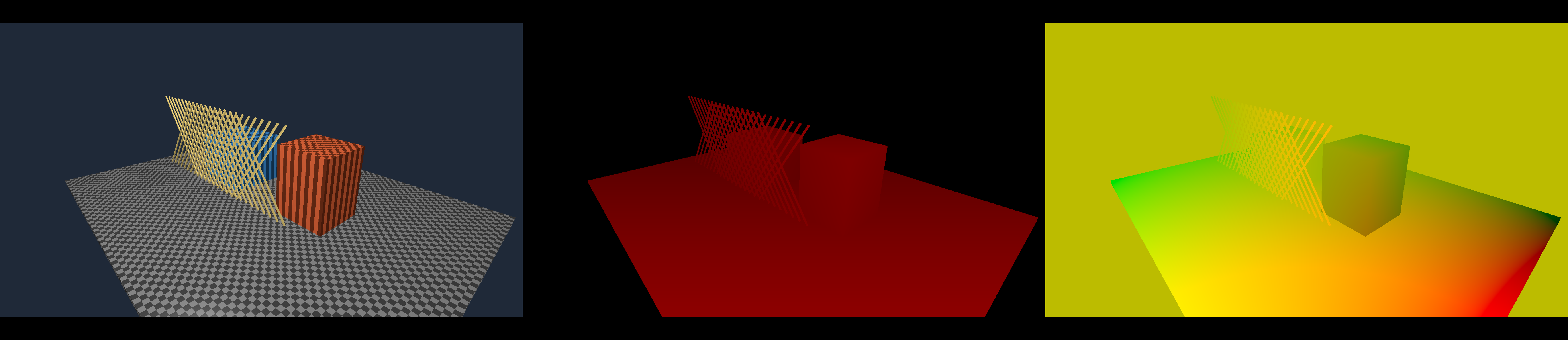
How the strip was made
The capture runs the reconstruction_plumbing starting point with its single blit replaced by three blitToScreen(attachment = …, viewport = …) calls, one per attachment, each with a ColorGrade exposure and offset to bring depth and motion into a visible range. Without NGX (this Mac), the source is native resolution.
This example writes depth into an R32F color attachment as well as using an ordinary depth-test attachment. That makes the sampled guide and its background convention explicit. A compatible sampled D32F depth image is also accepted by the adapter.
| Image | What it contains | What it must not stand in for |
|---|---|---|
| Color | Opaque, linear HDR RGB; alpha one; pre-exposure supplied explicitly | Latent pigment coordinates, coverage, or already composited UI |
| Depth | Standard Vulkan projected depth in [0,1], background 1 | Distance in world units, a reversed-Z buffer without conversion |
| Motion | Previous pixel position minus current pixel position, in input pixels, X right / Y down | Optical flow substituted without validating correspondences |
An existing RGBA-only target is the first of the three pieces, not all of them: you have to produce the depth and motion too. Constant depth and zero motion are the right answer for a fixed plane, and only for a fixed plane — an animated fragment function needs motion vectors that describe what it animated.
Make jitter and motion agree
Reconstruction asks for slightly different subpixel observations of the scene. Each rendered frame uses:
val jitter = ReconstructionJitter.halton(frameIndex, inputSize, outputSize)The sample's vertex shader projects each point at the current and previous camera/object state, keeping those two clip positions unjittered for motion. Only the raster position receives jitter:
gl_Position = nowClip;
gl_Position.xy += vec2(2*jitter.x/inputWidth, -2*jitter.y/inputHeight)
* gl_Position.w;
The Y sign here follows Field's Vulkan viewport convention. The fragment shader converts the unjittered positions into top-left-origin UVs, then input-pixel displacement:
vec2 nowUV = nowClip.xy / nowClip.w * vec2(.5, -.5) + .5;
vec2 prevUV = oldClip.xy / oldClip.w * vec2(.5, -.5) + .5;
motion = (prevUV - nowUV) * inputSize;
depth = gl_FragCoord.z;
A point moving four input pixels right must write (−4, 0). Keep object transforms as well as camera transforms from the previous rendered frame. Jitter goes into rasterization and the ReconstructionFrame value; it does not go into these motion vectors. The starting point's shaders contain the complete version, including background pixels.
A shader can change color without moving a surface. Motion vectors cannot describe that change, and you should not invent geometry motion to stand for it. For a deliberate discontinuity, reset history or draw that layer after reconstruction. UI, coverage-dependent effects, and imagery whose temporal character must remain untouched are also good candidates for a later pass.
Record producer, then consumer
The starting point installs one Target in renderer.renderList.preTargets. Its render method owns the sequence:
neural.evaluate(
    command,
    index,
    source,
    ReconstructionInputs(
        source.imageViewArray[0],
        source.imageViewArray[1],
        source.imageViewArray[2],
    ),
    ReconstructionFrame(frameIndex, jitter, revision = sceneRevision),
)
This overload of evaluate renders source first, then reconstructs its completed attachments on
the same graphics queue. It rejects a source independently registered in preTargets, so that the
source is rendered once. Evaluation handles the NGX output's storage/read transitions and validates
sizes, formats, sampled usage and the single mip/layer contract. Its output is an ordinary Field RenderToTexture:
neural.output.blitToScreen(name = "finished image")To use the output in another module, bind it through the usual fromViews texture resolver and schedule that consumer after evaluation. Keep tone mapping, UI and later compositing there.
Advance the frame index and previous transforms when this target actually records a frame. A coroutine tick while a window is minimized is not a new rendered observation.
Extend the graph to Ray Reconstruction
Open the rr_plumbing starting point. It reuses the Fabricate scene and RTXDI lighting, and converts their outputs into the formats and conventions RR expects in a moduleHere() you can edit. The five guide attachments are:
| Attachment | Format | Where it comes from in this starting point |
|---|---|---|
| 0: depth | R32F | Fabricate position attachment's projected depth in .w |
| 1: motion | RG32F | -velocity.xy * inputDimensions from Field's current-minus-previous UV velocity |
| 2: diffuse albedo | RGBA16F | Actual linear RGB albedo of the Lambertian (purely diffuse) lighting |
| 3: specular albedo | RGBA16F | Zero RGB because this lighting has no specular lobe |
| 4: normal + roughness | RGBA16F | World-space unit normal in RGB; roughness one for this lighting |
The source is the raw RTXDI output. The conversion module samples surface data with nearest filtering rather than inferring materials from the finished RGB image. Zero specular and roughness one are true of this diffuse lighting and of nothing glossier, so read those two rows as this scene's values and not as a template. The current adapter does not supply optional specular hit distance.
scene.bundle.gBuffer.render(command, index)
scene.lighting.render(command, index)
guides.render(command, index)
rr.evaluate(
    command,
    ReconstructionInputs(
        scene.lighting.output,
        guides.imageViewArray[0],
        guides.imageViewArray[1],
    ),
    ReconstructionFrame(frameIndex, jitter, revision = sceneRevision),
    RayReconstructionGuides(
        guides.imageViewArray[2],
        guides.imageViewArray[3],
        guides.imageViewArray[4],
        scene.bundle.scene.camera.modelView(),
        scene.bundle.scene.projection.evaluateUniform(),
    ),
)
The camera matrices passed to RR remain unjittered. Fabricate's separate rasterJitterNdc supplies the raster offset. All these inputs describe the same frame and the same BRDF. The starting point unregisters each of these passes from the renderer, so that its own Target records them in this order.
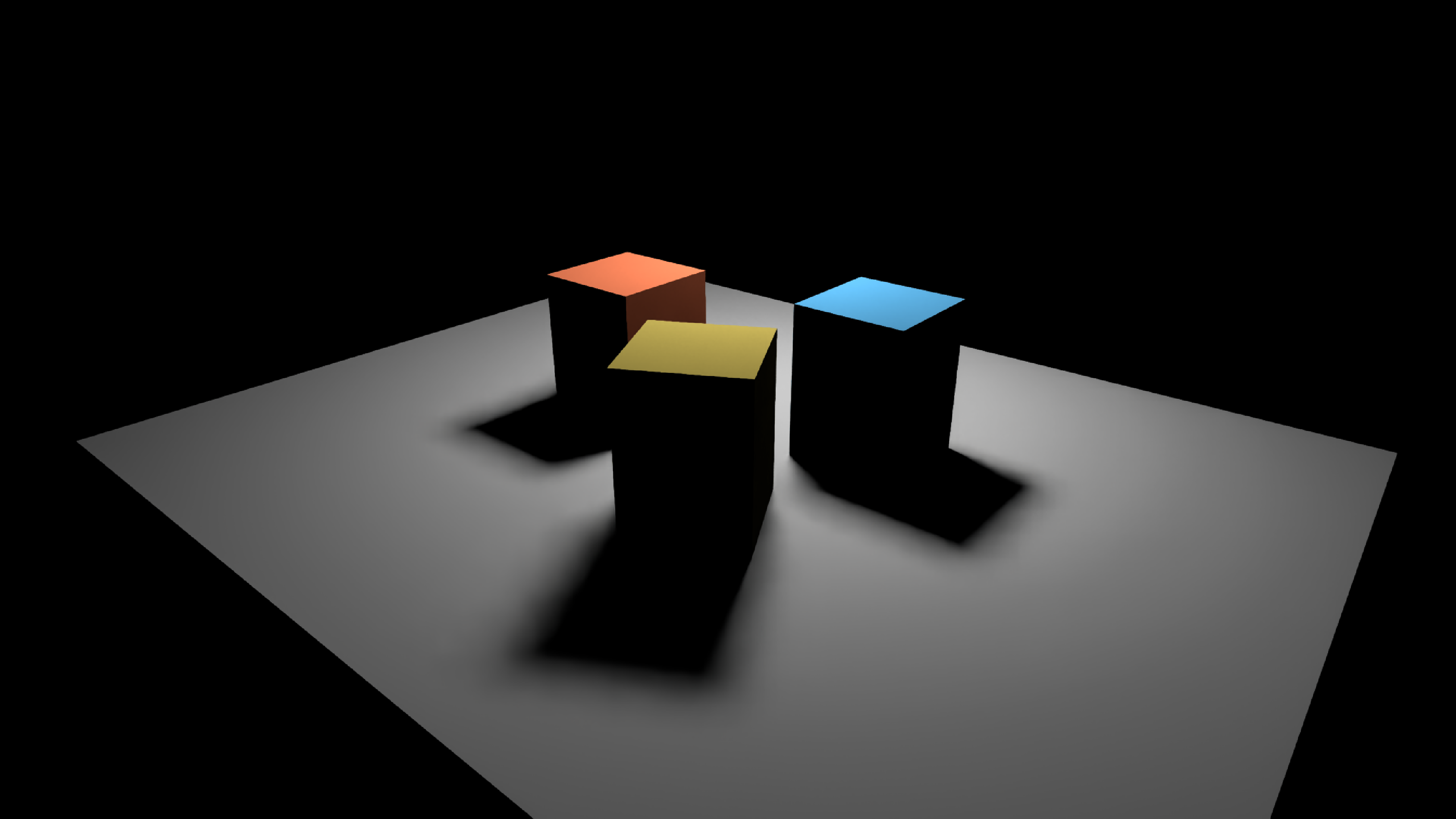
RR is created with rayReconstruction = true and is queried separately from SR. This starting point uses native 1080p so you can inspect the guide conversion without also changing render resolution. Bypass to raw lighting immediately exposes the unfiltered signal. RR replaces the denoising/reconstruction stage; the example neither spatially filters its input nor adds DLAA afterward.
History and ownership belong to the graph
The adapter owns its NGX view and reconstructed output; your graph owns source images, guide images, modules and meshes. Use one context per temporal view. Stop/recreate it at a frame boundary, and keep inputs alive until submitted GPU work completes. Remove scheduled passes before closing the adapter, then retire your own Vulkan resources through renderer.cleanup. Have that cleanup closure capture the exact allocation and renderer it was created with: reading a box property at cleanup time gets you whatever a rerun put there, or nothing at all if the parent has already stopped.
Call reset("reason") for camera cuts, semantic shader/material edits and bypass transitions. A changed scene revision also resets history. The adapter detects replaced input images, skipped frame indices and resumed presentation. Size, mode or format changes require a new context and compatible targets. The starting points watch shader changes and include an explicit Cut / reset history button; after changes to bound textures or lighting semantics, use that button too. Layout changes require rerunning the box to rebuild its resources.
A failed compatible shader compilation retains Field's last working module. Once a change succeeds, invalidate history. The SDK returns success for a reversed motion sign, a misread guide, or the wrong color space, so inspect the inputs yourself and compare movement against bypass.
Where learned shaders fit
The learned shader workflow replaces a function that produces RGB. It can therefore replace a color-producing pass in this graph, but its output does not manufacture depth, motion, normals or BRDF guides. Keep those producers, and ensure that they still describe the image being reconstructed.
For the current (screen x, screen y, parameter) → RGB network, camera and other unrepresented inputs are fixed during training. It is not a learned scene representation that supports arbitrary new camera motion. Train and inspect that approximation first, then decide whether temporal reconstruction improves its intended look. The learned model, SR and RR are independently bypassable tools.
The editable starting points are the reference implementations for this page; read them before writing your own. The SR and RR pages carry measured GPU costs and their limits.