Building geometry in the headset
Written for the visionOS app
Everything here runs inside Field4Vision's Live Metal head on an Apple Vision Pro, which is where the shader, the uniforms and the finished image live. See Field on Apple Vision Pro for the app itself.
The geometry is the exception: Preview Vision Geometry builds your mesh on your Mac and shows it to you, headset or no headset.
A Live Metal program has three parts, and you write each one somewhere different:
| Part | Where |
|---|---|
| shader | the box's msl property — Metal Shading Language, both entry points |
| geometry | geometry { … } in the box's Kotlin, which runs in the headset |
| uniforms | the uniforms= list on the box's // {{ visionmetal }} marker |
This page is about the middle one.
Why the geometry runs in the headset
Field can build a mesh on your Mac and send it to the Vision Pro. For geometry that changes every frame, it can also run the builder on the headset, avoiding a network transfer for every update.
The Kotlin in a // {{ visionmetal }} box runs on the headset. It compiles to
JavaScript and runs in a small JavaScriptCore context on the headset's render thread.
geometry { … } assembles vertices there and hands the finished arrays to Metal in a single call. The
network carries your program, once; it never carries vertices at frame rate.
That is why rebuilding a mesh every frame is affordable.
The smallest complete example
This box places one cube a little over a metre in front of you, off to the right, and passes the shader one animated
uniform, phase:
:::static
// {{ visionmetal uniforms=phase }}
onStart {
    geometry {
        color(1.0, 0.35, 0.15)
        cube(0.18, cx = 0.45, cz = -1.2, tintFaces = true)
    }
    onFrame { frame -> uniform("phase", frame.time * 3.0) }
}
Positions are in metres, in the space you launched the immersive scene in: -z is in front of you,
+y is up. So cz = -1.2 is 1.2m ahead, and 0.18 is a cube about the size of a grapefruit.
The matching shader goes in the box's msl property and reads u_phase. The head generates
#define u_phase frame.user[0] from the marker's uniforms= list, so shaders name their uniforms
instead of counting slots.
The builder surface
The whole of it, in one place. geometry { … } hands you a MeshBuilder with
twelve methods and nothing else, and the rest of this page is
those twelve in detail.
| Builder example | Behavior | Source |
|---|---|---|
normal(0.0, 0.0, 1.0) |
Sets the normal copied into every following vertex. This affects later appends and returns the builder for chaining. | VisionMetalKotlinJs.kt:67 |
color(0.9, 0.3, 0.2, 1.0) |
Sets the RGBA colour for subsequent vertices. Earlier vertices retain their stored colours. | VisionMetalKotlinJs.kt:73 |
uv(0.0, 1.0) |
Sets the texture coordinate copied by following vertex calls. It occupies v.uv.xy in the shader. |
VisionMetalKotlinJs.kt:79 |
extra(0.5, 1.0) |
Sets two free per-vertex values stored in v.uv.zw. Choose their interpretation in your own shader. |
VisionMetalKotlinJs.kt:85 |
val a = vertex(x, y, z) |
Appends a vertex with the current normal, colour, UV and extra state. Returns its index for later triangle or quad calls. | VisionMetalKotlinJs.kt:91 |
triangle(a, b, c) |
Adds one face from three existing vertex indices. Counter-clockwise winding faces the viewer; back faces are culled. | VisionMetalKotlinJs.kt:126 |
quad(a, b, c, d) |
Adds triangles (a,b,c) and (a,c,d). The four indices therefore determine both winding and the diagonal. |
VisionMetalKotlinJs.kt:132 |
clear() |
Drops all appended vertices and indices while retaining builder state. Use it before rebuilding geometry for another frame. | VisionMetalKotlinJs.kt:139 |
cube(half = 0.2, tintFaces = true) |
Appends an axis-aligned cube with edge length twice half. Separate face vertices preserve facet normals; optional tinting distinguishes the faces. |
VisionMetalKotlinJs.kt:151 |
plane(width = 1.0, height = 0.5, cols = 8, rows = 4) |
Appends an XY quad lattice facing positive z. Column and row counts set the tessellation density. | VisionMetalKotlinJs.kt:192 |
sphere(radius = 0.2, segments = 24, rings = 16) |
Appends a UV sphere with smooth shared normal directions. Segments and rings control angular tessellation. | VisionMetalKotlinJs.kt:220 |
tube(points, radius = 0.02, sides = 8) |
Sweeps a polygon along a polyline to give it thickness. Fewer than two points appends nothing. | VisionMetalKotlinJs.kt:260 |
The first four set state and return the builder, so they chain and apply to everything appended after them. The next three build faces from indices. The last four append whole shapes.
clear() drops the appended geometry while keeping the current normal, colour and uv, which is what
a per-frame rebuild wants when every frame starts from the same material. The vertex layout is
fixed, so no builder method adds a new attribute; extra() is the escape hatch, as Per-vertex
channels explains.
Vertices and indices
Underneath the shape helpers is a plain indexed-triangle builder.
vertex(x, y, z) appends a vertex and returns its index. It takes the builder's current
normal(), color(), uv() and extra() state, so you set those once and append many vertices:
:::static
geometry {
    normal(0.0, 0.0, 1.0)
    color(0.9, 0.3, 0.2)

    val a = vertex(-0.1, -0.1, -1.0)
    val b = vertex(0.1, -0.1, -1.0)
    val c = vertex(0.1, 0.1, -1.0)
    val d = vertex(-0.1, 0.1, -1.0)

    quad(a, b, c, d) // == triangle(a, b, c) + triangle(a, c, d)
}
Winding is counter-clockwise as seen from the front; the head culls back faces, so a face wound the other way is invisible. If a shape appears to have holes in it, that's the first thing to check, and the preview will check it for you.
Because faces reference vertices by index, you choose your own normals:
- Share vertices between faces and the normals interpolate — a smooth surface.
- Duplicate them per face, each with its own normal, and the edges stay crisp — facet shading.
This is what
cube(tintFaces = …)does, which is why its six sides read as flat.
vertexCount and indexCount are readable as you go, which is the easiest way to sanity-check a
generator:
:::static
log("built $vertexCount vertices, ${indexCount / 3} triangles")
Per-vertex channels
Each vertex carries four float4s, and the shader sees them as FieldVertex:
| Builder call | MSL | Notes |
|---|---|---|
vertex(x, y, z) |
v.position |
Writes the position with homogeneous .w = 1. The appended vertex receives the current values of every other channel. |
normal(x, y, z) |
v.normal |
Sets the normal for subsequent vertices with .w = 0. The shader can transform it as a direction. |
color(r, g, b, a) |
v.color |
Sets linear RGBA colour for subsequent vertices. Alpha is available to the fragment shader alongside RGB. |
uv(u, v) |
v.uv.xy |
Sets the two texture coordinates for subsequent vertices. Their mapping to a texture is chosen by the shader. |
extra(first, second) |
v.uv.zw |
Sets two additional scalar channels. Use them for per-vertex phase, weight or another shader-specific value. |
extra() is the escape hatch. There is no way to add a new attribute to the vertex layout from a
box, so when you need to get one more number per vertex into the shader (a band index, an age, a
random seed), put it there.
The shape helpers
These append to whatever is already in the builder, so you can combine them freely in one mesh.
:::static
geometry {
    color(1.0, 0.42, 0.18)
    cube(0.11, cx = -0.42, cz = -1.2, tintFaces = true)

    color(0.25, 0.75, 1.0)
    sphere(0.13, segments = 32, rings = 20, cx = -0.14, cz = -1.2)

    color(0.95, 0.85, 0.25)
    plane(0.26, 0.26, cols = 8, rows = 8, cx = 0.14, cz = -1.2)
}
cube(half, cx, cy, cz, tintFaces)— an axis-aligned cube of edge2 * half. Facet normals, one set of four vertices per face.tintFacescolours each face from its normal, which is a cheap way to tell orientation while you're getting a shader working.plane(width, height, cols, rows, cx, cy, cz)— a quad lattice on the XY plane facing+z, with uv spanning the whole sheet. Raisecols/rowswhen a vertex shader needs something to deform.sphere(radius, segments, rings, cx, cy, cz)— a UV sphere with smooth (shared) normals.tube(points, radius, sides)— see below.
Tubes: a line with real thickness
tube sweeps a polygon along a polyline. It's the same treatment Field's native FLine viewer gives a
stroke, and the reason a curve drawn in Kotlin looks like an object in the headset rather than a
hairline:
:::static
geometry {
    color(0.62, 0.42, 1.0)
    tube(
        (0..48).map { i ->
            val t = i / 48.0
            val a = t * 6.2831853
            p(0.42 + 0.055 * sin(a), -0.13 + t * 0.26, -1.2 + 0.055 * cos(a))
        },
        radius = 0.017,
        sides = 10,
    )
}
p(x, y, z) builds a point. sides is the cross-section's polygon count, and 6 to 10 is plenty at arm's
length. uv runs around the tube in u and along the spine in v, so a shader can put a
travelling band on it with in.uv.y. Fewer than two points draws nothing rather than erroring.
Rebuilding
Call geometry { … } again whenever you like, including from onFrame:
:::static
onFrame { frame ->
    geometry {
        color(0.2, 0.9, 0.8)
        tube(spineAt(frame.time), radius = 0.012, sides = 8)
    }
}
The swap happens at a frame boundary, so a rebuild never tears — you will not catch a half-built mesh on screen.
Reach for a rebuild when the spine or the topology changes, which is the part a shader cannot do for you. If the motion is only a transform (rotating, scaling, displacing along a normal) the shader does it for one uniform and no rebuild. Cost scales with the mesh. A few hundred to a couple of thousand vertices per frame is comfortable; at tens of thousands, rebuild on demand and let the shader animate.
An empty builder is a legitimate way to draw nothing:
:::static
geometry {} // clears the mesh
There is no fallback to a built-in cube. A box that never calls geometry { … } draws nothing,
and the head says so once. The Vision Geometry: Built-in Cube command drops in a known-good mesh
when you want to work out whether the problem is your shader or your geometry, and Preview Vision
Geometry comes at the same question from the other side (see
below).
A procedural mesh, start to finish
Height fields are the shape most procedural geometry takes, so here it is in full, including normals by finite difference, which saves differentiating your surface by hand:
:::static
// {{ visionmetal uniforms=spin,light }}
import kotlin.math.cos
import kotlin.math.exp
import kotlin.math.sqrt

onStart {
    geometry {
        val n = 48
        val size = 0.52
        val centreZ = -1.2

        fun height(x: Double, z: Double): Double {
            val r = sqrt(x * x + z * z)
            return 0.055 * cos(r * 38.0) * exp(-r * 5.5)
        }

        val step = size / n
        val eps = step * 0.5
        val base = vertexCount

        for (row in 0..n) {
            for (col in 0..n) {
                val x = (col.toDouble() / n - 0.5) * size
                val z = (row.toDouble() / n - 0.5) * size
                val h = height(x, z)

                // Central differences give the two tangents; their cross product is the normal.
                val dx = (height(x + eps, z) - height(x - eps, z)) / (2.0 * eps)
                val dz = (height(x, z + eps) - height(x, z - eps)) / (2.0 * eps)
                val len = sqrt(dx * dx + dz * dz + 1.0)
                normal(-dx / len, 1.0 / len, -dz / len)

                val t = (h / 0.055 + 1.0) * 0.5
                color(0.15 + 0.75 * t, 0.35 + 0.35 * t, 0.95 - 0.35 * t)

                uv(col.toDouble() / n, row.toDouble() / n)
                vertex(x, h, centreZ + z)
            }
        }

        // This sheet lies in XZ with its normal on +y, so the corners have to go round this way.
        // The other diagonal winds it face-down and the head culls the whole landscape away.
        val stride = n + 1
        for (row in 0 until n) {
            for (col in 0 until n) {
                val a = base + row * stride + col
                quad(a, a + stride, a + stride + 1, a + 1)
            }
        }
    }

    uniform("light", 0.35, 0.9, 0.35)
    onFrame { frame -> uniform("spin", frame.time * 0.25) }
}
Note the import kotlin.math.… lines above the onStart. kotlin.math is not a default import, and
imports go at the top of the box, under the marker.
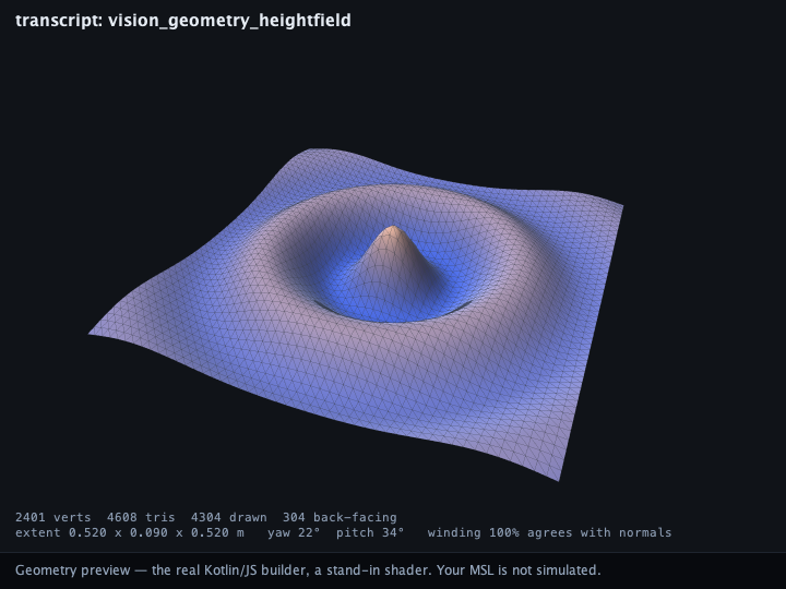
Previewing it on your desk
The Preview Vision Geometry command builds the mesh on your Mac rather than in the headset. It takes the box's Kotlin, compiles it to JavaScript with the same compiler a live box uses, runs it against a mirror of the head's JavaScriptCore bridge, and rasterizes the mesh that comes out, into the box's own output.
It previews your geometry, not your shader
The mesh is the real one, the packed vertex array your headset would have received from the same builder. The shading is a stand-in, a fixed two-light lambert over your vertex colours. Your MSL is not compiled, translated or simulated here. This answers "is my geometry the shape I meant?"; Vision Geometry: Built-in Cube answers the other half on the device.
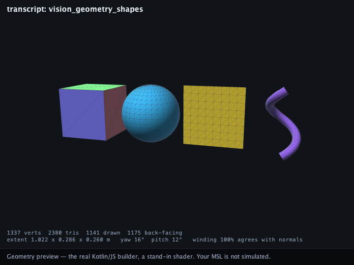
From Kotlin, the same thing is one call:
:::static
val capture = previewVisionGeometry(source = myLiveMetalProgram)
val mesh = capture!!.mesh()
println("built " + mesh.vertexCount + " vertices, " + mesh.triangleCount + " triangles")
capture.meshes holds every upload in order, so a box that rebuilds in onFrame gives you one mesh
per tick and you can watch the shape move:
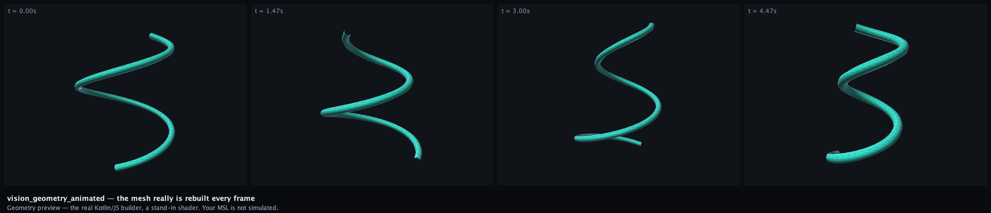
Or all ninety of them, at the rate the head would have rebuilt them. The stats line under the mesh is recomputed per frame, so the vertex count and the winding agreement move with the shape. That is how you catch a rebuild that only goes wrong at one phase of the motion:
Winding and invisible faces
The preview culls back faces because the head does. That reproduces the most common way a mesh goes wrong: a face wound the other way is simply not there.
Worse, it can be convincingly not there. A closed shape wound inside-out still draws a plausible
solid — you are looking at the inside of its far side. So the preview also measures the mesh against
itself: for every triangle it compares the winding's implied direction with the normal() you
declared, and reports the fraction that agree. A clean mesh normally reads 100%; a lower number
points you toward faces whose winding or normals need checking. The number is printed on the frame.
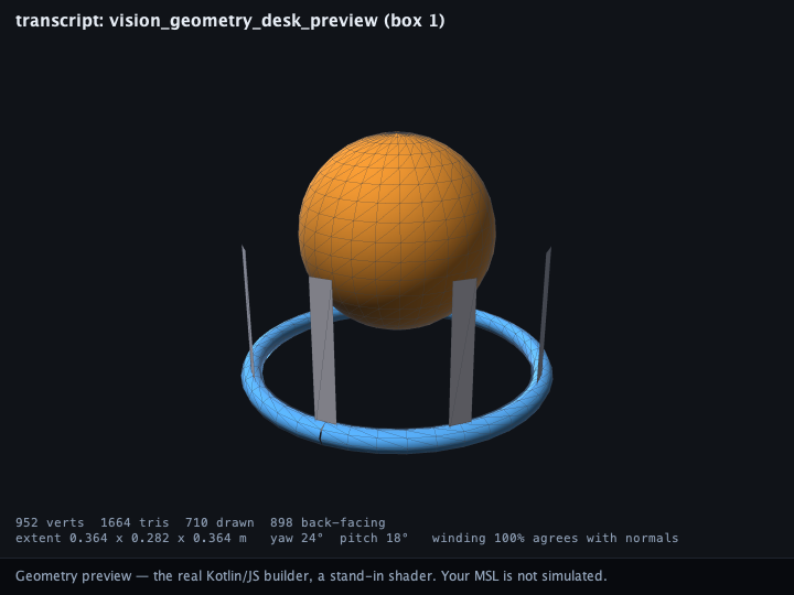
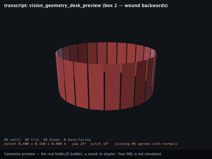
Here is the pair. The same lantern built correctly (a sphere on a ring, 952 vertices, winding 100% agrees with normals), and then with the ring wound backwards, drawn with culling disabled so you can see what the head would have thrown away:
Uniforms that don't line up
The other thing the preview checks needs no picture at all. A uniform is named in three places (the
marker's uniforms= list, the shader's u_NAME, and the script's uniform("name", …)), and each
mismatch fails differently and late:
| Mismatch | What the head does |
|---|---|
shader reads u_NAME, marker doesn't declare it |
no #define is emitted; Metal fails to compile your shader |
| script writes a name the marker doesn't declare | there is no slot; the write is dropped and the shader reads zero |
| marker declares a name nothing uses | a wasted slot — reported, but harmless |
shader has no field_vertex / field_fragment |
the head refuses to build a pipeline |
VisionMetalProgramCheck decides all of those from the box's own text plus a real run of its script,
and Preview Vision Geometry reports them alongside the mesh. It does not compile MSL (that still
happens on the device), but the mistakes above never reach the compiler in the first place.
A turntable, and the mesh as FLines
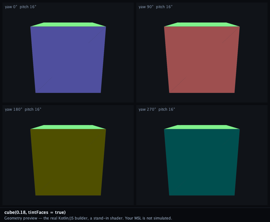
VisionGeometryPreview.renderContactSheet draws the same mesh from several angles at once, which is
the quickest way to be sure a shape is a solid and not a lucky projection:
And if you would rather measure the mesh than look at it, CapturedMesh.toFLines() hands its unique
edges (in metres, with vertex colour) to Field's own 3-D viewer, where the rest of Field's drawing
and geometry tools apply.
Runnable starting points
Each of these is a complete document (geometry, shader and uniforms) you can open and edit, and between them they are the examples this page is drawn from.
- visionos_start — the smallest complete program: a cube, a shader, one animated uniform. Open ↗
- vision_geometry_shapes — cube, sphere, plane and tube side by side, with a shader that reads the uv the shapes write. Open ↗
- vision_geometry_heightfield — the procedural mesh above, in full. Open ↗
- vision_geometry_animated — a swept tube rebuilt from scratch every frame. Open ↗
- vision_geometry_desk_preview — the preview above, without a headset: one box builds a lantern and draws it in its own output, the next builds the same ring wound backwards so you can see what the winding check catches. Open ↗
Agents: where the pictures come from
Every preview on this page is a committed capture from the vision.geometry-preview FIELD_TEST, by
the route a live box takes: the box's Kotlin compiled by the real KotlinToJsCompiler, the emitted
JavaScript run under node against a mirror of LiveMetalJavaScript.swift, and the resulting packed
vertex array rasterized. Four of the five documents above supply their Kotlin to it verbatim, out of
the shipped agent transcripts.
VISION_GEOMETRY_PREVIEW_DIR=public/docs/assets/vision_geometry python3 tools/run_field_tests.py --id vision.geometry-previewThe FIELD_TEST asserts as well as draws: the mesh invariants, the analytic vertex and triangle
counts of every shape primitive, the packed stride against both VISION_METAL_VERTEX_FLOATS and
the Swift LiveMetalVertex declaration, and image-level facts about each raster (painted fraction,
colour spread, and for the sphere the roundness and area of its silhouette). Every entry's winding
fraction is asserted too, so a primitive that starts winding the other way fails the build.
Further reading
- Field on Apple Vision Pro — the app, and the other native surfaces.
- Kotlin in the Head — how a
// {{ … }}box compiles and runs remotely. - Agent Transcript Gallery — the whole starting-point corpus.