Geometry from disk
Have a mesh file you want to explore? Load it into a Field box and show it in one line:
showMesh("/path/to/thing.glb")That reads the file, assembles it, and puts a shaded render you can orbit into the box's output area, with the mesh's measurements printed underneath. Keep the mesh instead of the picture and everything in the mesh family applies: weld it, measure its volume, decimate it, shoot a ray at it, write it back out as something else.
What reads what
| you have | the call | what you get back | works headless |
|---|---|---|---|
.obj |
meshFromFile(path) |
TriMesh, index-for-index with the file |
yes |
.stl (ASCII or binary) |
meshFromFile(path) |
TriMesh, triangle soup — see below |
yes |
.ply (ASCII, binary, either endianness) |
meshFromAnyFile(path) |
TriMesh with the file's per-vertex colours |
yes |
.glb, .gltf, .fbx, .dae, .3ds, … |
meshFromAnyFile(path) |
TriMesh, all parts baked through their node transforms |
yes |
| any of the above, textured, with PBR materials | gltfModelHere("…") / the Fabricate renderer |
GPU buffers, materials, textures, a live scene | no — needs a renderer |
.step, .iges, .brep |
nothing | — | — |
meshFromAnyFile handles everything meshFromFile does and more, so if you are unsure, use it.
meshFromFile is the pure-Kotlin reader with no native library behind it. Where each loader lives
in the source is at the end of the page.
showMesh opens the mesh in a Three.js viewer you can orbit. It uses the same viewer as
threeLines(...), so a mesh and its annotations can share a scene. For a still image drawn on the
CPU, pass renderer = MeshRenderer.CPU; TriMesh.renderPng and the inline toHTML() card use
that renderer too.
A real GLB, in a real output area
This example loads the Khronos ToyCar sample, the same GLB the Fabricate renderer renders with full PBR materials. It has three mesh/material buckets, a draped cloth with a lot of folds, glass, and every part positioned by a node transform rather than baked into the vertices:
:::static
/*
The same file public/docs/fabricate_renderer.md renders with full PBR — here through the plain
Three.js viewer instead, which is `showMesh`'s default and gives you a solid you can orbit.
`renderer = MeshRenderer.CPU` for the static z-buffer figure, which needs no GPU at all.
*/
val glb = java.io.File("public/docs/assets/fabricate_demo/ToyCar.glb")
println("${glb.name}: ${glb.length()} bytes on disk")

val car = meshFromAnyFile(glb.path)
println(car.summary())

// Three mesh/material buckets, assembled by node transform rather than heaped at the origin.
val b = car.bounds()
println(
    "assembled extent %.4f x %.4f x %.4f metres"
        .format(
            b.max.x - b.min.x,
            b.max.y - b.min.y,
            b.max.z - b.min.z,
        ),
)
:::fold draw it
showMesh(
    car,
    view = MeshView(width = 560, height = 420, wireframe = false),
    title = "ToyCar.glb — 108,936 triangles in the Three.js viewer",
)
:::endfold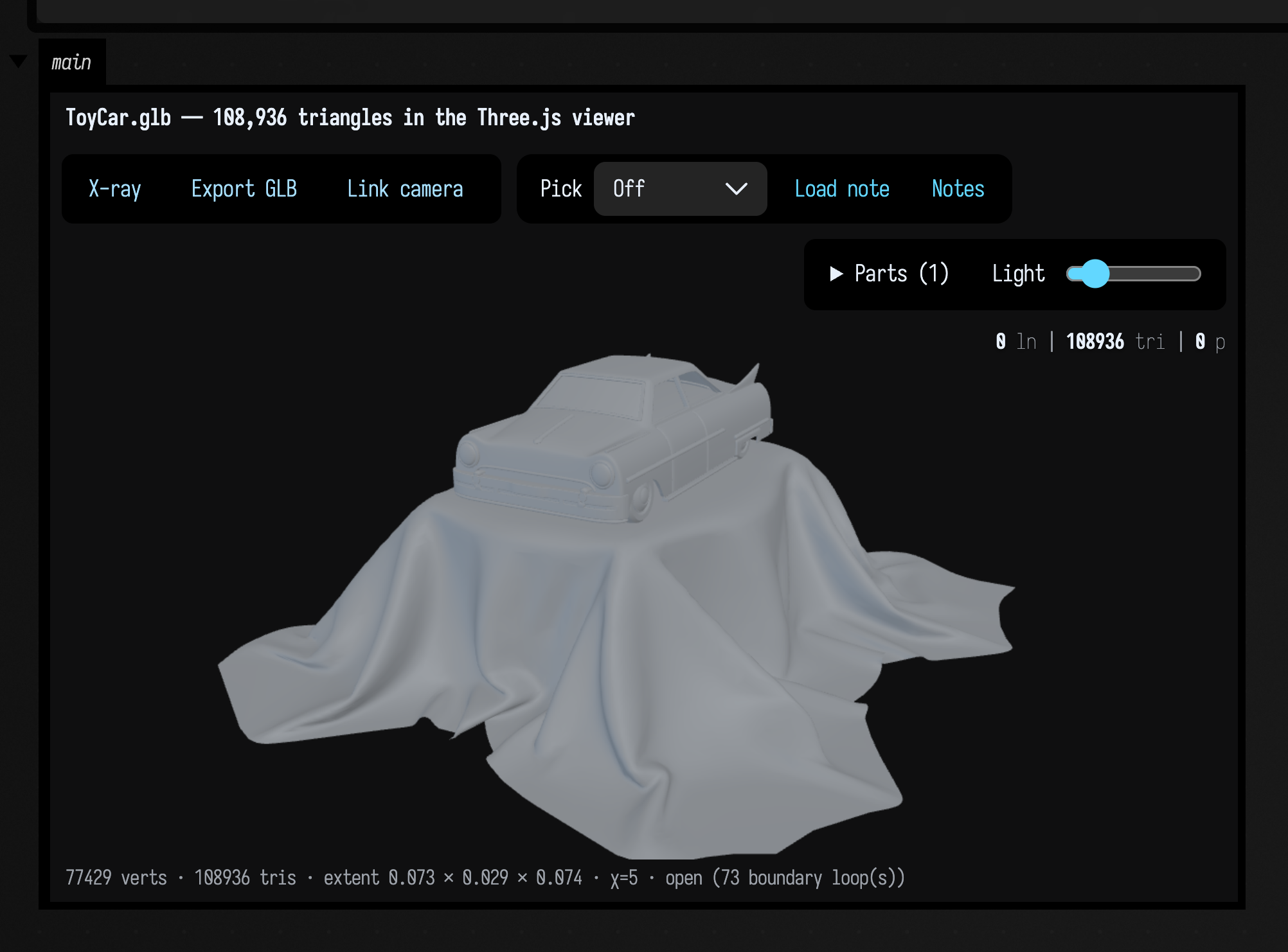
The caption under the picture is the mesh's own measurements:
- 77,429 vertices, 108,936 triangles (326,808 indices), summed over the three buckets: ToyCar itself at 66,951 vertices, Fabric at 8,959 and Glass at 1,519.
- extent 0.073 × 0.029 × 0.074 — the file is in metres, and it is a 7 cm toy.
MeshView'sdistanceis measured in bounding-sphere radii, so the camera frames it correctly without your having to know that.normalized(2.0)is there if you want a common scale across several models. - χ = 1909, open, 2782 boundary loops. χ is the Euler characteristic. An artist's model is a
shell rather than a solid, and every UV seam and every hard edge is a real cut in the surface. Expect this of anything that came out of a
modeller, and do not reach for
repaired()unless you actually need watertightness (for a volume, a boolean, or a printer).
Loading a glTF without a renderer
GltfSupport.loadGltfBasic(path) with default arguments cannot run outside a live renderer.
GltfLoadConfig.loadTextures defaults to true, and that path asks the box context for a
Renderer so it can build stub textures. From a plain function, a test, or a headless script it
therefore dies with a bare NullPointerException that says nothing about textures. Pass
GltfLoadConfig(loadTextures = false) and geometry-only loading works everywhere.
assimpToTriMesh does exactly that for you.
What happens to a glTF scene
A glTF file is a node hierarchy: each node carries a full 4×4 transform, several nodes can
reference the same mesh, and each mesh carries its own material. Flattening that into one TriMesh
keeps some of it and drops the rest. The table says what meshFromAnyFile does with each part,
checked on a small scene of one asymmetric triangle instanced by an identity node, a translated node,
a child of that translated node, and a mirrored node with scale (-1, 1, 1).
| the scene has | the bridge does |
|---|---|
| several nodes referencing meshes | merges all of them. Four instances arrive as 4 triangles in 4 components, not "the first one". |
| a node transform | applies it. ToyCar's own three nodes each carry a uniform 1e-4 scale, so a bridge that dropped transforms would render the figure above 10,000× too big: 730 m across, not 0.073 m. |
| a parent chain | composes it. The child of the node translated by (3, 0, 0), itself translated by (0, 2, 0), lands at (3, 2, 0). |
| a mirror — negative determinant | applies it, and reverses that part's winding, so the surface still faces outward instead of being culled away. |
| non-uniform scale | normals go through the inverse transpose, not the matrix, so they stay perpendicular to the surface. |
per-vertex COLOR_0 |
kept, per instance. An all-white array — what glTF writes when the file has no colours — is dropped. |
| quads or n-gons | already triangles: Assimp's aiProcess_Triangulate runs before the bridge sees anything. |
| materials and textures | dropped. A TriMesh has no concept of a texture. Use the Fabricate renderer for those. |
| animation | dropped. The bind pose is baked; node TRS tracks and skinning are not read. |
| a Y-up / Z-up disagreement | nothing. glTF is Y-up by specification and no axis conversion is applied, so a Z-up PLY or OBJ arrives on its side. rotated(...) is yours to apply. |
Placing instances yourself: bindMatrix, not bindPose
bindPose is a translation / rotation / scale triple, and a mirror does not fit in one —
Matrix4f.getScale is a sqrt per basis column, so it is never negative. A mirrored node
arrives with 3×3 determinant −1.0 and bindPose.toMatrix() gives it back at +1.0: the
reflection is gone, the instance is placed un-mirrored, and nothing warns you. bindMatrix is
the un-decomposed world matrix, and it is what assimpToTriMesh and the GPU paths read.
FabricateTransform is itself a TRS triple, so FabricateTransform.set(Matrix4f) checks its
own decomposition and keeps the original matrix when recomposing does not reproduce it. While
that override is in force the TRS fields are a lossy summary — mutating them in place does
nothing to what is drawn — and clearMatrix() goes back to composing them.
MeshInstance.applyToMesh defaults model to the instance's own node transform, so a glTF
scene positioned by its nodes assembles instead of stacking every part at the origin.
PlyModel.applyToMesh defaults to the identity, because PLY has no scene graph to drop.
The GPU path leaves two things alone, and MeshInstance.bindMatrix's KDoc in
simpleGLTFSupport.kt has the reasoning: winding is not reversed for a negative-determinant
instance (every Field pipeline sets VK_CULL_MODE_NONE), and normals are mat3(modelView) * n
rather than the inverse transpose, which is exact for a rigid, uniformly-scaled or mirrored node
and skewed for a non-uniformly scaled one.
Writing a file and reading it back
What comes back from a file is not always what went out. This example writes a coloured sphere to OBJ and STL, reads both back, and compares them.
In a document of your own, name the file and let Field place it: "ball.obj".file lands in the
document's own files/ folder next to the boxes that made it (File
management). The examples here write to a temp directory instead.
:::static
// A coloured sphere, out to both formats and back. Nothing is written into the repository: this is a
// temp directory that the box deletes at the end.
val dir = java.nio.file.Files.createTempDirectory("mesh-round-trip").toFile()
val source = icosphereMesh(3, 1.0).withColor(0.3, 0.7, 1.0)

val objFile = java.io.File(dir, "ball.obj").also { source.saveObj(it) }
val stlFile = java.io.File(dir, "ball.stl").also { source.saveStl(it) }
println("ball.obj  ${objFile.length()} bytes")
println("ball.stl  ${stlFile.length()} bytes   (= 84 + 50 x ${source.triangleCount})")
println()

// meshFromFile picks the reader by extension. meshFromAnyFile would too, and also reads .ply/.glb.
val viaObj = meshFromFile(objFile.path)
val viaStl = meshFromFile(stlFile.path)
val welded = viaStl.weld(1e-5)

// A lambda rather than a local `fun`, because inside a box `println` is rewritten onto the box's own
// receiver and a nested function does not have it.
val row = { label: String, m: TriMesh ->
    "%-16s %5d verts  %5d tris  normals=%-5s colours=%-5s chi=%-5d %s  volume %.6f"
        .format(
            label,
            m.vertexCount,
            m.triangleCount,
            m.hasNormals,
            m.hasColors,
            m.topology().eulerCharacteristic,
            if (m.isWatertight()) "watertight" else "open      ",
            m.signedVolume(),
        )
}
println(row("source", source))
println(row("via .obj", viaObj))
println(row("via .stl", viaStl))
println(row("via .stl, welded", welded))
:::fold draw the three of them side by side, then clean up
showMeshGrid(
    "source — icosphereMesh(3), coloured" to source,
    "via ball.obj — colours gone" to viaObj,
    "via ball.stl, welded — normals gone" to welded,
    columns = 3,
    cellWidth = 235,
)
dir.deleteRecursively()
:::endfold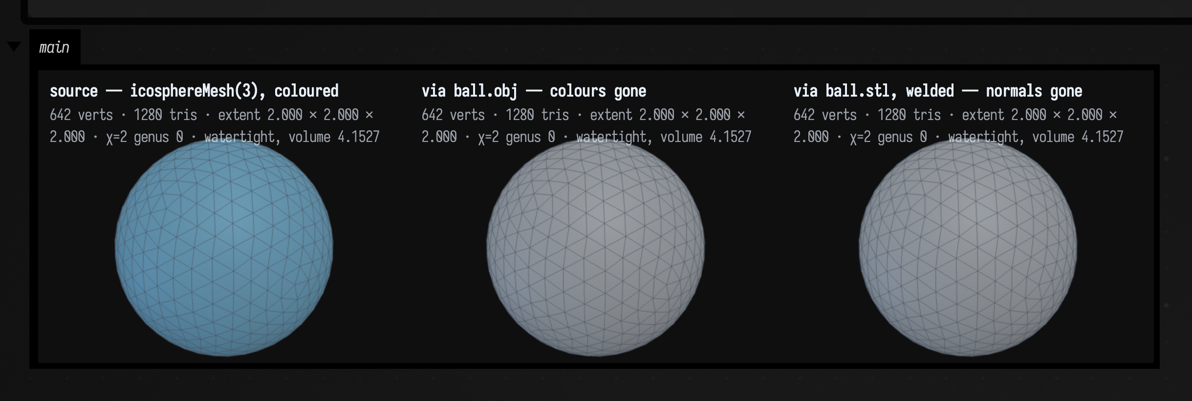
Each difference between the pictures is something a format cannot carry.
What each format loses
Measured on icosphereMesh(3, 1.0).withColor(0.3, 0.7, 1.0), which is 642 vertices, 1280 triangles,
area 12.506493 and volume 4.152741:
| Representation | verts | tris | normals | uvs | colours | χ | closed | area | volume |
|---|---|---|---|---|---|---|---|---|---|
| source | 642 | 1280 | yes | — | yes | 2 | watertight | 12.506493 | 4.152741 |
via .obj |
642 | 1280 | yes | yes¹ | no | 2 | watertight | 12.506493 | 4.152741 |
via .stl |
3840 | 1280 | no | no | no | 1280 | open | 12.506493 | 4.152741 |
via .stl, weld(1e-5) |
642 | 1280 | no | no | no | 2 | watertight | 12.506493 | 4.152741 |
¹ uvs survive OBJ when the mesh has them; this sphere does not. A heightfieldMesh round-trips its
uvs to within 1e-5.
The coordinates always survive: area and volume are identical to six decimal places through every route, so a mesh whose shape changed on a round trip is a bug and not a format.
OBJ keeps structure and loses colour. It indexes positions, normals and uvs separately, so Field's
reader emits one vertex per distinct (position, uv, normal) corner — which is why a hard-edged cube
from a modeller faithfully comes back with 24 vertices and not 8. There is no standardised
per-vertex colour in OBJ, so withColor never reaches the file. STL keeps nothing but triangles: no
vertex sharing at all, so 1280 triangles become 3840 unshared vertices and every edge reads as a
boundary. weld(1e-5) recovers the topology exactly but not the normals, because STL never stored
one per vertex, so re-shade after welding — shadedNormals(35.0) is usually right. PLY is the format
that carries colour, which is generally why a file is a PLY at all: it is what photogrammetry and
scanners emit, and meshFromAnyFile routes .ply through PlySupport rather than Assimp for that
reason.
File size for the same 1280 triangles, with binary STL's exactly 84 + 50n bytes as the floor:
| Format | bytes |
|---|---|
binary .stl |
64,084 |
.obj |
75,625 |
ASCII .stl |
324,825 |
Where the counts come from
summary(), toFigureHtml() and the inline toHTML() card compute topology on the mesh you hand
them rather than remembering what it was, so a format artefact arrives looking like a property of
your model:
icosphereMesh(3).summary()

// 642 verts, 1280 tris, extent 2.0000 …, chi=2, genus 0, watertight, area 12.5065, volume 4.1527, …

stlToTriMesh(icosphereMesh(3).toStlBinary()).summary()

// 3840 verts, 1280 tris, extent 2.0000 …, chi=1280, genus 0, open(1280), area 12.5065, …
The second line has no volume, because summary() only prints one for a watertight mesh, but
signedVolume() on the same soup still returns 4.152741: no geometry was lost. genus 0 is
correct too, because 1280 separate triangles are 1280 discs, each of genus 0.
An unexpected vertex count is usually shading rather than the file. Writing and reading are faithful, so look upstream at what shaded the mesh:
| Construction | vertices |
|---|---|
boxMesh() |
8 |
boxMesh().shadedNormals(35.0) |
24 |
boxMesh().flatShaded() |
36 |
objToTriMesh(boxMesh().toObj()) |
8 |
objToTriMesh(boxMesh().shadedNormals(35.0).toObj()) |
24 |
flatShaded() un-welds every triangle, so a solid stops being watertight and its Euler
characteristic becomes its triangle count. Save the unshaded mesh and let the renderer crease-shade
it, or weld after reading.
PLY: colours, point clouds and missing normals
This example writes a four-vertex coloured square as ASCII PLY, reads it back with PlySupport, and
converts it to a TriMesh. In a document of your own, "square.ply".file is the form to use.
:::static
// A four-vertex coloured square, written as ASCII PLY and read back. The same code path a 10-million-
// point scan takes; small enough to read here.
val dir = java.nio.file.Files.createTempDirectory("ply-demo").toFile()
val file = java.io.File(dir, "square.ply")
file.writeText(
    """
    ply
    format ascii 1.0
    element vertex 4
    property float x
    property float y
    property float z
    property uchar red
    property uchar green
    property uchar blue
    element face 2
    property list uchar int vertex_indices
    end_header
    0 0 0 255 40 40
    1 0 0 40 255 40
    1 1 0 60 60 255
    0 1 0 255 235 40
    3 0 1 2
    3 0 2 3
    """
        .trimIndent() + "\n",
)

// The loader is PlySupport — no renderer, no Vulkan, no Box context needed.
val model = PlySupport.loadPly(file.path)
val b = model.buffers
println(
    "vertices ${b.vertexCount}, indices ${b.indexCount}, colours ${b.hasColors}, " +
        "normals in the file ${b.hasNormals}, point cloud ${b.isPointCloud}",
)
println(
    "packed as ${b.vertexData.capacity() / (b.vertexCount * 4)} floats per vertex: " +
        "[pos.xyz][normal.xyz][color.rgba]",
)

// ...and the bridge into a TriMesh keeps the colours.
val mesh = model.toTriMesh()
println("as a TriMesh: ${mesh.summary()}")
println("colours survived: ${mesh.hasColors}, vertex 0 is ${mesh.color(0)}")
println(
    "normals dropped: ${!mesh.hasNormals} — the file had none, and the loader's " +
        "invented (0,0,1) would shade the whole thing as if it faced you",
)
:::fold draw it flat on, then clean up
showMesh(
    mesh,
    view = MeshView(yawDegrees = 0.0, pitchDegrees = 0.0, width = 420, height = 315),
    title = "square.ply — per-vertex colours",
)
dir.deleteRecursively()
:::endfold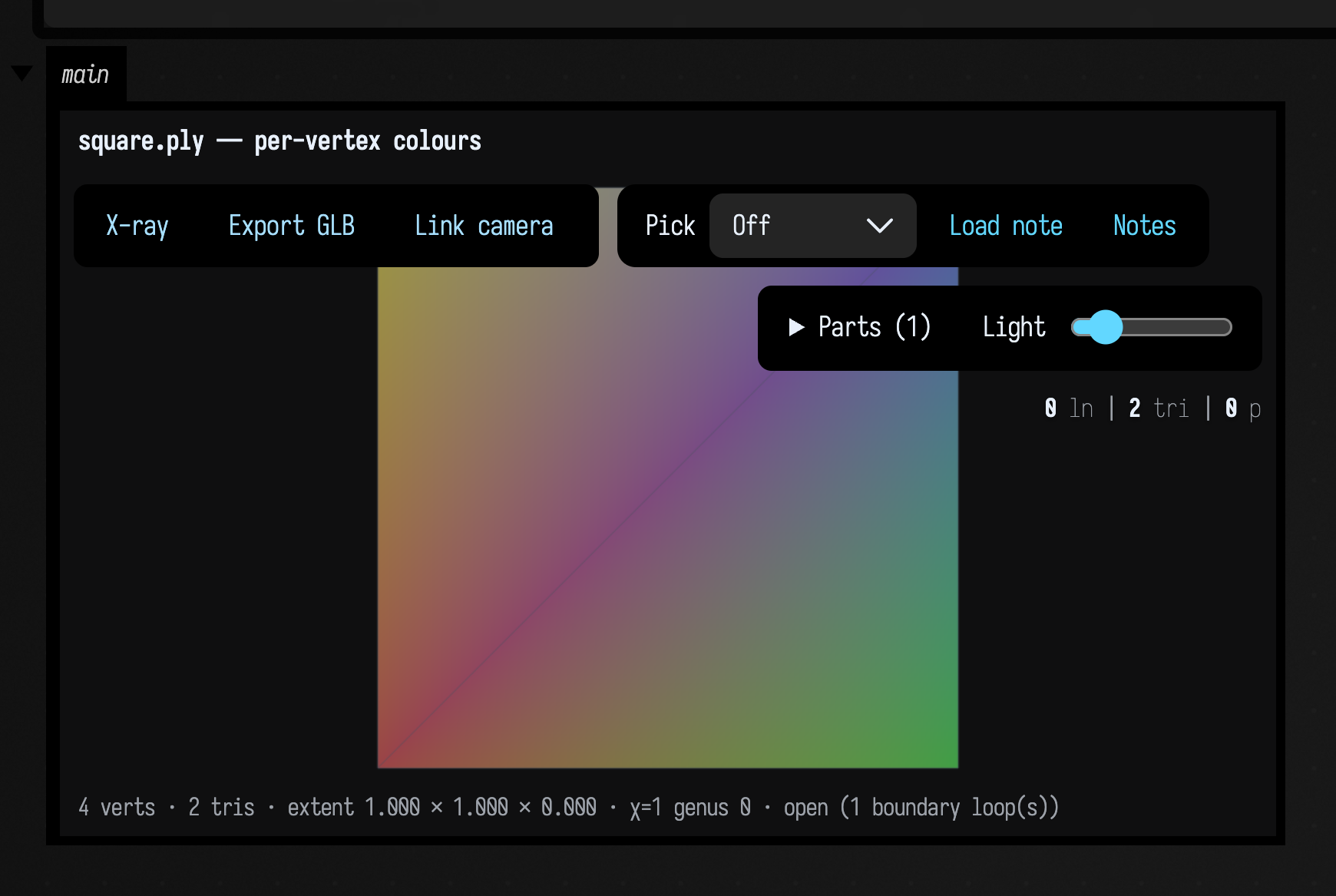
Three details in that output are easy to miss:
- A PLY with no normals gets
(0, 0, 1)written for every vertex by the loader. That is a wrong normal rather than a missing one, and a wrong normal shades the whole model as though it faced the camera.toTriMesh()drops them when the file had none, so the render bridges crease-shade for you instead. PasskeepNormals = falseto drop them even when the file has them. - A PLY with no
faceelement is a point cloud, andtoTriMesh()says so rather than handing back a mesh with no triangles. Checkbuffers.isPointCloudfirst; for drawing those, theplyPointCloudHeremacro renders them on the GPU as camera-facing quads. - All-white colours are dropped. Both bridges do this. A glTF with no
COLOR_0, or a PLY with nored/green/blue, gets white written for every vertex by its loader — that carries no information and would only override the renderer's own shading with a flat white.
Missing formats and missing features
STEP, IGES, BREP and other CAD formats are not read. A .step file is NURBS surfaces trimmed
against each other rather than a mesh, and Field has no CAD kernel. Export STL from FreeCAD or your
CAD tool and read that. meshFromAnyFile on a .step throws rather than returning an empty mesh.
Textures and materials do not come across into a TriMesh, which has positions, normals, uvs and
per-vertex colours only; assimpToTriMesh drops the material. For a textured, rendered model use
gltfModelHere and the StandardRenderer; the
Renderers reference page lists that path's declarations.
Point clouds are read by PlySupport and drawn on the GPU by plyPointCloudHere, but there is
no CPU point-cloud type, no surface reconstruction, and no downsampling. convexHullMesh over the
positions and voronoi3d are what there is.
Gaussian splats are better served. SplatRaster (SplatRaster.kt) renders a
splat cloud on the CPU into PNG bytes, matching the GPU renderer's framing for the same Config.
SplatContactSheet puts a whole capture in one image, and SplatCloud lets you crop, filter,
decimate, transform and merge a cloud and write a .compressed.ply back out.
Animation is not kept. GltfSupport.MeshInstance.animationSamples carries the node tracks
Assimp reads, but assimpToTriMesh bakes the bind pose, and skinning is not read at all.
Stepping through a mesh pipeline has no viewer of its own. showMeshGrid (several meshes side
by side) and showMeshTurntable (one mesh from four angles) show the stages statically.
Export is OBJ and STL only: toObj, saveObj, toStlAscii, toStlBinary and saveStl.
Neither keeps per-vertex colours. The .compressed.ply writer above is for splats, not triangles.
Fixing a mesh that looks wrong
Most of these show up in summary(), so print it before you draw anything.
| symptom | cause | what to do |
|---|---|---|
contains no obj geometry |
the file is not what its extension says | A ZIP, a glTF or an HTML error page saved as thing.obj: the message says what it looks like. meshFromAnyFile reads most formats by their contents. |
| holes, or whole faces missing | inside-out winding, open mesh | Back faces are culled exactly as a GPU culls them, so a wrongly-wound patch is not dark, it is gone. fixWinding(), then check topology().isConsistentlyOriented. |
| looks fine, every measurement negative | inside-out winding, closed solid | The silhouette is unchanged and both renderers flip inward normals rather than shading them black, so the picture is no help at all. signedVolume() < 0 is the only tell; fixWinding() is the fix. |
| flat, faceted or oddly uniform shading | no normals, or invented ones | A mesh with none is crease-shaded for you; one with wrong ones is not. Recompute with shadedNormals(35.0). To drop them, copy(normals = null), or withoutAttributes() for every attribute. |
isWatertight() false on a closed solid |
it came through STL | Or it was flatShaded() before it was written. weld(1e-5) recovers the topology, and meanEdgeLength() is the scale that tells you 1e-5 is safe rather than a guess. |
| the vertex count is exactly 3× | STL, or flatShaded() |
Both un-weld every triangle, and the reader on the other side will not weld it back. weld, then shadedNormals if you want the hard edges again. |
From a file on disk to a solid you can cut
To use a loaded mesh in a boolean, it has to be closed: toSolid() refuses anything
that is not. Two calls do the repair automatically. diagnose() says what is wrong, and
repairToSolid() fixes what it can and reports what it could not:
val mesh = meshFromAnyFile("scan.glb")
println(mesh.diagnose().report()) // why, worst first
val fixed = mesh.repairToSolid()
println(fixed.report()) // what was done, and what was not
if (fixed.isSolid) display(fixed.mesh.toSolid() - drill)
Defect severities: what blocks a solid
diagnose() sorts what it finds by severity. A blocking defect is one Manifold rejects; the
others it accepts, though some of them still deserve a look.
| defect | severity | what it means |
|---|---|---|
NON_FINITE_POSITION |
blocking | a NaN or infinite coordinate |
UNWELDED_VERTICES |
blocking | coincident vertices with different indices — until they merge, every seam reads as a hole |
DUPLICATE_FACE |
blocking | two triangles with the same corners; each extra copy makes its three edges non-manifold |
NON_MANIFOLD_EDGE |
blocking | an edge with three or more faces |
OPEN_BOUNDARY |
blocking | a hole |
UNWALKABLE_BOUNDARY |
blocking | boundary edges in no closed ring |
DEGENERATE_FACE |
suspicious | zero-area triangles — Manifold accepts these |
NON_MANIFOLD_VERTEX |
suspicious | a pinch point — Manifold accepts these |
INVERTED_ORIENTATION |
suspicious | closed but wound inward — Manifold accepts this |
MULTIPLE_COMPONENTS |
informational | disjoint pieces — Manifold accepts these and sums the volumes |
UNREFERENCED_VERTEX |
informational | vertices no triangle uses |
The dangerous suspicious row is INVERTED_ORIENTATION: an inside-out closed mesh is a legal
manifold, and Manifold hands back a negative volume without throwing, after which a boolean
computes the complement of what you meant. toSolid() refuses it for that reason (pass
check = false to take it anyway); fixWinding() flips it.
UNWALKABLE_BOUNDARY usually means inconsistent winding rather than anything exotic. Tracing a
boundary into a ring follows directed half-edges, so a wrongly wound patch breaks the trace and an
ordinary hole reports as unwalkable. Run fixWinding() and diagnose again before reading it as two
holes meeting at one vertex.
The repair steps, in order
repairToSolid() runs these steps in this order, because each later step gives a wrong answer
without the earlier ones:
| step | fixes | does not fix |
|---|---|---|
weld |
unwelded seams, STL-style unshared vertices | anything, until it has run: hole and component counts are meaningless before it |
removeDegenerateTriangles |
zero-area faces | — |
removeDuplicateFaces |
duplicated faces; a back-to-back pair cancels to nothing | — |
removeNonManifoldFins |
dangling flaps (a non-manifold edge and a boundary edge on the same triangle) | two closed sheets meeting on an edge — that needs a modelling decision, so it is left alone and reported |
fixWinding |
inconsistent orientation | — |
fillHoles |
open boundary loops | a non-planar or self-intersecting rim gets a cap it flags as suspect |
fixWinding again |
inside-out components | — |
The second fixWinding does different work from the first. Its outward-facing stage only flips a
component that is closed, because "outward" is undefined for an open sheet, so before the caps
exist every holed component is skipped. Running it again afterwards is what stops a repaired mesh
coming back inside out with a negative volume.
Hole filling is the part to be suspicious of. Each ring is reversed (a cap must walk its boundary edges the opposite way to the surface), given a Newell normal, projected into that plane and ear-clipped; if ear clipping stalls, a centroid fan closes it anyway. Two failure modes are detected and reported:
- a non-planar rim gets a flat cap over a wavy hole. The mesh is a valid solid; the volume is
wrong.
BoundaryLoopInfo.planaritymeasures the deviation against the loop's own diameter before the fill happens, so the warning is available in advance. - a self-intersecting rim is what makes ear clipping stall, and the fan that closes it can pass through itself.
A ring that repeats a vertex is neither: it is a figure-eight, two holes pinched together, and capping it as one polygon creates a non-manifold edge — the repair would make the mesh worse. Those are split at the repeats first, so each real hole gets its own cap.
A sound cap can still be the wrong shape
Nothing about a hole says whether its end should be a flat cap or whether the model continued there. These two cases have equally clean caps and opposite outcomes:
| Input surface | rim | cap | cap share of surface | result |
|---|---|---|---|---|
| uncapped cylinder | flat | clean ear clip | 16.5% | volume error 0.00000 — exactly right |
| torus with its tube severed | flat | clean ear clip | 2.7% | volume error 4.2%, and genus 1 becomes 0 |
Planarity, fill method, edge count and cap area are all as good or better on the wrong one, so no
cap-area threshold could flag the torus without also flagging the cylinder. capAreaFraction is
reported, but does not set isSuspect.
So isSuspect == false means the cap's geometry is sound, not that the model is the one you
started with. Only a comparison against the shape you meant catches the difference.
What repairToSolid does
repairToSolid() builds on repaired(), which welds vertices, removes degenerate faces and
unused vertices, and fixes winding. It also closes open boundaries and handles non-manifold edges
caused by duplicated faces or dangling fins.
It refuses rather than guesses on two shapes: a NaN position, because repairing around it would
silently delete the affected triangles and cap the gap, and two closed tetrahedra sharing a face.
Both report the failure instead of returning something that looks repaired.
Most broken meshes repair to the shape they came from. The ones that come back valid but the wrong shape have curved or non-planar holes, where a fan fill is doing the best it can; a crowned rim can be off by a third of its volume.
Where the repair measurements are
The table of deliberately broken meshes, what each row is broken in, and the per-row residuals
are in dev_docs/MESH_REPAIR_MEASUREMENTS.md.
Repairing ToyCar
ToyCar.glb (77,429 vertices, 108,936 triangles, 2,197 components, 42,104 boundary edges in 2,782
traced loops) repairs to a valid solid you can boolean: 21,047 vertices welded, 84 holes closed
with 3,668 triangles.
A valid solid can still differ from the intended shape. Here nine of the 84 caps are flagged as
suspect, including a 335-edge centroid fan the size of a body panel. There is no undamaged original
to compare against, so check result.suspectFills before relying on the reported volume of
3.16e-5.
Seeing it
Box.showMeshDiagnosis(mesh) puts the mesh, painted by defect, beside the ordered list of what is
wrong. TriMesh.defectFLines() gives the same information as drawable lines to lay over your own
drawing: red for boundary loops, orange for non-manifold edges, magenta for pinched figure-eight
loops, yellow (opt-in) for winding disagreements. TriMesh.withDefectColors() is the per-vertex
colouring the card renders, if you want it in your own picture.
This example removes a patch of faces from a sphere, leaves one more face unwelded, and shows the diagnosis:
:::static
// A sphere with a patch of faces removed, and one more face left unwelded — the two commonest
// ways a mesh off disk fails. Built here rather than loaded, so the picture needs no file.
val base = icosphereMesh(3, 1.0)
var broken = base.filterTriangles { it >= 4 }

// Give triangle 0 its own three vertices: the crack an STL export leaves at every seam.
val pos = broken.positions.copyOf(broken.positions.size + 9)
val idx = broken.indices.copyOf()
for (k in 0..2) {
    val v = broken.indices[k]
    val d = (broken.vertexCount + k) * 3
    pos[d] = broken.x(v)
    pos[d + 1] = broken.y(v)
    pos[d + 2] = broken.z(v)
    idx[k] = broken.vertexCount + k
}
broken = TriMesh(pos, idx)

println(broken.diagnose().report())
:::fold draw it
/*
No `view` argument, and that is the point: the camera aims itself at the worst defect. The hole
is on the far side from the default three-quarter view, so without that this figure would be a
photograph of an apparently perfect sphere captioned "4 faces removed".
*/
showMeshDiagnosis(broken, title = "4 faces removed, plus one unwelded face")
:::endfold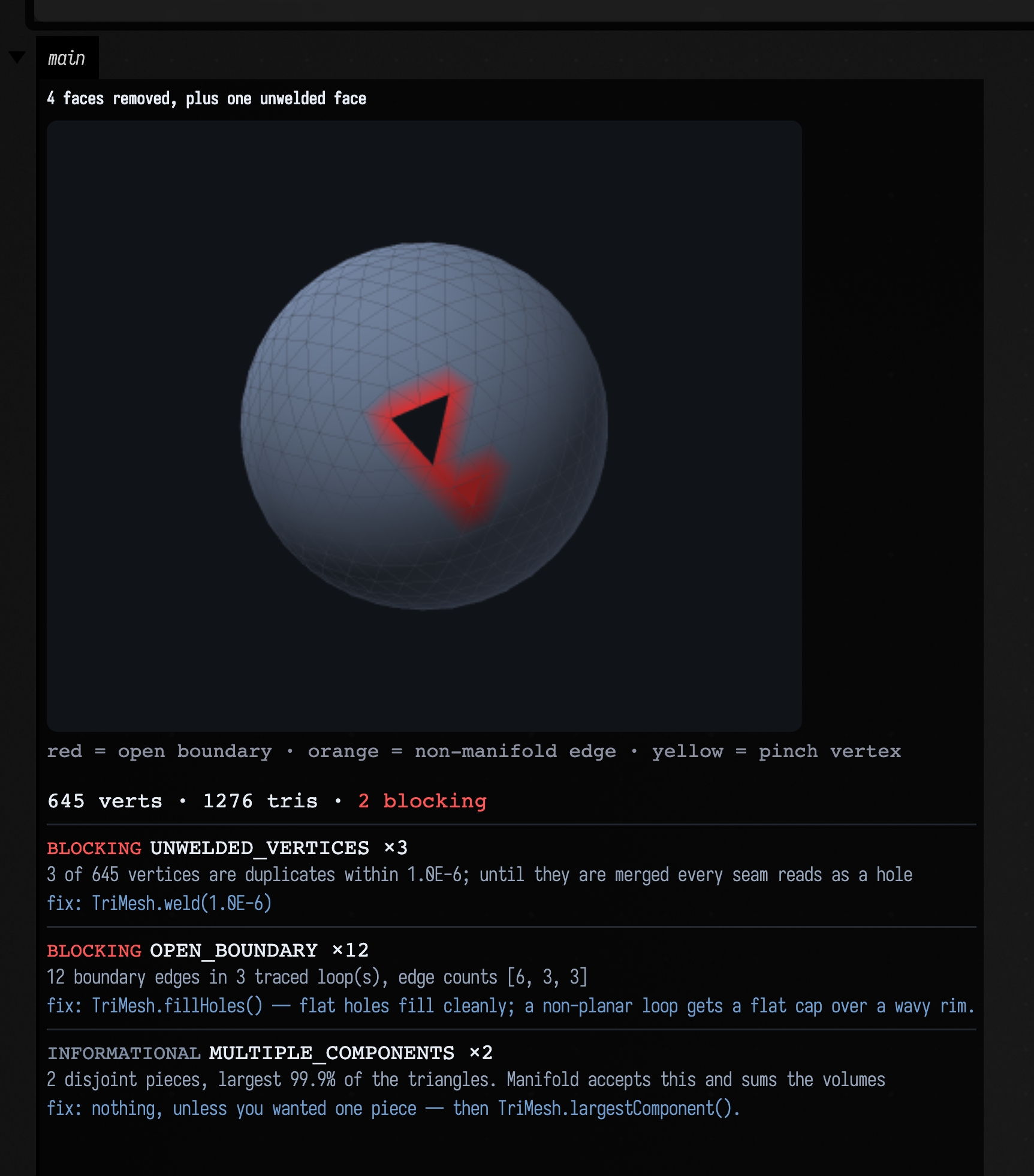
showMeshDiagnosis points the camera at the worst defect unless you pass a view, which is why
the hole is in shot above: it sits on the far side of the sphere from the default three-quarter
view. TriMesh.defectFacingView() is that camera, if you want it for your own render. The red halo
and the smaller red patch are the two blocking rows of the list beside it.
Open this to see it
The mesh_repair_demo starting point holds two boxes: one damages a sphere and shows the diagnosis
card, the other repairs it, prints what was done, and cuts the result. Both run with no files and no
network.
What it costs
Reading a mesh off disk is cheap enough to do in a live box on every re-run. Measured on an M-series laptop, five reads after two warm-up reads:
| Loader and input | file | triangles | time | rate |
|---|---|---|---|---|
ToyCar.glb via Assimp |
5.4 MB binary | 108,936 | 83 ms | 1310 k tri/s |
big.obj via meshFromFile |
9.4 MB text | 132,488 | 337 ms | 393 k tri/s |
big.stl via meshFromFile |
6.6 MB binary | 132,488 | 185 ms | 718 k tri/s |
big.obj via assimpToTriMesh |
the same 9.4 MB | 132,488 | 223 ms | 595 k tri/s |
Binary reads about twice as fast as text for the same mesh, so prefer STL over OBJ for an
intermediate file nobody reads. Assimp's native OBJ reader is faster than the Kotlin one, but
meshFromAnyFile still routes .obj to the Kotlin reader, because it round-trips a file
index-for-index. If you are reading
hundreds of OBJs in a loop, assimpToTriMesh on them directly is the faster call.
Drawing it on the CPU costs more than reading it:
| Rendering operation | on 108,936 triangles |
|---|---|
renderPng(560×420, wireframe = false) |
51 ms |
renderPng(560×420, wireframe = true) |
114 ms |
toFigureHtml(…) — what showMesh(renderer = MeshRenderer.CPU) calls |
419 ms |
Most of the figure's cost is the caption: its χ, genus, watertightness and boundary-loop count
need a full topology pass over the whole mesh. If you are re-rendering in a loop and do not need the
numbers, call renderPng and display the image yourself.
The default showMesh uploads the mesh to the Three.js viewer once; the browser can then redraw
it as you orbit. The caption still needs its topology pass.
Writing back out
Three calls cover the export formats:
// java.io is not in a box's default imports, hence the qualified names.
mesh.saveObj(java.io.File("/tmp/thing.obj")) // keeps normals and uvs; loses colours
mesh.saveStl(java.io.File("/tmp/thing.stl")) // binary; positions only; every slicer reads it
java.io.File("/tmp/thing.stl").writeText(mesh.toStlAscii()) // ~5x larger, human-readable
Write the un-shaded mesh: flatShaded() triples the vertex count and un-welds the surface, and
the reader on the other side will not weld it back. For a printer, check isWatertight() and that signedVolume() is positive before writing: a
consistently-oriented but inside-out solid looks completely normal in a render (the silhouette is
unchanged and the rasterizer flips inward normals rather than shading them black) and reports a
negative volume. fixWinding() is the fix.
Agents: where the pictures and counts come from
Each figure is a box's own output area, captured by the docs build running the fence above it.
The ToyCar figure reads the committed assets/fabricate_demo/ToyCar.glb; replace that file and
the page's counts describe a different car. The counts are pinned in
src/jvmTest/kotlin/afield/geometry/mesh/MeshFromDiskTest.kt, and MeshIoTest.kt covers the reader
behaviour they rest on.
Trying it yourself
The ToyCar, round-trip and PLY examples are also a document you can open from the geometry_from_disk
starting point, with the same three boxes live. Point the first box's path at a
mesh file of your own and re-run it, or change the second box's weld tolerance or the third's corner
colours, and watch the numbers and the picture change. Boxes two and three write only into a temp
directory they delete themselves.
Internals: where the loaders live
Four separate pieces of code read geometry off disk:
| loader | source | reads | produces |
|---|---|---|---|
| stdlib mesh I/O | afield/geometry/mesh/mesh_io.kt |
OBJ, STL | TriMesh |
| PLY | afield/graphics/scene/simplePLYSupport.kt |
PLY, meshes and point clouds | packed 10-float GPU buffer |
| Assimp / glTF | afield/graphics/scene/simpleGLTFSupport.kt |
glTF, GLB, FBX, DAE, 3DS, OBJ, STL, PLY, … | packed 12-float GPU buffer + materials |
| Fabricate | afield/graphics/scene/fabricated/FabricateGltfBridge.kt |
the Assimp model above | FabricateScene for the PBR StandardRenderer |
The PLY and Assimp loaders produce ordinary host memory rather than Vulkan allocations, so their
buffers need no renderer even though their textures do. afield/graphics/scene/MeshFromDisk.kt
turns them into a TriMesh: PlyModel.toTriMesh(), assimpToTriMesh(path), the meshFromAnyFile
dispatcher, and the showMesh(path) overload at the top of this page. A box calls all of these with
no import. The CPU renderer is VisionGeometryPreview, a z-buffer whose output is deterministic.
Reference
Read, any format
Load a mesh through the format-dispatching entry point.
| Entry point | Behavior |
|---|---|
meshFromAnyFile(path) |
Loads OBJ, STL, PLY or an Assimp-supported scene into a CPU TriMesh. Scene parts are baked through their transforms; unreadable paths throw instead of returning an empty mesh. |
fun Box.showMesh(mesh: TriMesh, channel: String = "main", view: MeshView = MeshView(), caption: String? = null, title: String? = null, renderer: MeshRenderer = MeshRenderer.GPU, height: Int = 430) |
Push a rendered view of mesh to one of this box's output channels, with its measurements as a caption. API. |
assimpToTriMesh(path, keepColors = true) |
Flattens a supported scene file into a TriMesh, applying node transforms, keeping per-vertex colours where the file has them. Textured materials do not survive the flattening. Those need the renderer path. |
fun VoronoiLattice.toTriMesh(shrink: Double = 0.92, boundedOnly: Boolean = false): TriMesh |
Every cell of a 3D Voronoi lattice as one TriMesh, one connected component per cell. API. |
Read, no dependencies
Read OBJ or STL through the direct readers when no native scene importer is needed.
| Entry point | Behavior |
|---|---|
fun meshFromFile(path: String): TriMesh |
Load a mesh from a path, choosing the reader by extension (.obj, .stl). API. |
fun triMeshFromObj(file: File): TriMesh |
Read an OBJ file — see objToTriMesh for what survives. API. |
fun objToTriMesh(text: String): TriMesh |
Parse Wavefront OBJ text into a TriMesh. API. |
fun triMeshFromStl(file: File): TriMesh |
Read an STL file, ASCII or binary — see stlToTriMesh. API. |
fun stlToTriMesh(bytes: ByteArray): TriMesh |
Parse STL, ASCII or binary — the format is sniffed, not declared. API. |
Write
Write OBJ or STL files for other tools. Check the format comparison above before relying on preserved normals or colours.
| Entry point | Behavior |
|---|---|
fun TriMesh.toObj(name: String = "mesh", decimals: Int = 6): String |
This mesh as Wavefront OBJ text: v positions, then vn normals and vt uvs if present, then f faces with 1-based indices. API. |
fun TriMesh.saveObj(file: File, name: String = file.nameWithoutExtension) |
Write this mesh to file as OBJ. Creates parent directories. API. |
fun TriMesh.toStlAscii(name: String = "mesh"): String |
This mesh as ASCII STL. One facet per triangle with its face normal, no vertex sharing (the format has none). API. |
fun TriMesh.toStlBinary(header: String = "Field afield.stdlib mesh_io.kt"): ByteArray |
This mesh as binary STL: an 80-byte header, the triangle count, then 50 bytes per triangle (little-endian float normal, three float positions, a zero attribute short). API. |
fun TriMesh.saveStl(file: File) |
Write binary STL to file. Creates parent directories. API. |
Look at it
Inspect shape and appearance in an output panel.
| Entry point | Behavior |
|---|---|
fun Box.showMesh(mesh: TriMesh, channel: String = "main", view: MeshView = MeshView(), caption: String? = null, title: String? = null, renderer: MeshRenderer = MeshRenderer.GPU, height: Int = 430) |
Push a rendered view of mesh to one of this box's output channels, with its measurements as a caption. API. |
fun Box.showMeshGrid(vararg panels: Pair<String, TriMesh>, channel: String = "main", columns: Int = 2, cellWidth: Int = 380, view: MeshView = MeshView(), renderer: MeshRenderer = MeshRenderer.GPU) |
Several meshes side by side, each rendered and captioned — the fastest way to see a whole pipeline (generated / subdivided / smoothed / decimated) side by side. API. |
fun Box.showMeshTurntable(mesh: TriMesh, channel: String = "main", views: List<MeshView> = MeshView.turntable(4), cellWidth: Int = 260, title: String? = null, renderer: MeshRenderer = MeshRenderer.GPU) |
A turntable contact sheet of one mesh: the same shape from views, laid out in a row. API. |
MeshView |
How to draw a TriMesh in a preview: where the camera stands and what the frame looks like. API. |
fun TriMesh.summary(): String |
A one-line factual summary of a mesh: counts, extent, topology and volume — the thing to print when you want the numbers rather than the picture. API. |
three(subject = mesh) |
Opens an orbitable Three.js view of a mesh. Use a scene block to combine solids and line annotations. |
threeGrid(…) |
Displays several subjects as titled viewports. |
threeTurntable(…) |
Displays a subject from a sequence of viewing directions. |
Look at it without a GPU
Render a still or an interactive figure using the CPU path when a native GPU renderer is unavailable.
| Entry point | Behavior |
|---|---|
fun TriMesh.renderPng(view: MeshView = MeshView(), caption: String? = null, title: String? = null): ByteArray |
This mesh rasterised to PNG bytes: perspective, z-buffer, two-light lambert shading over the per-vertex colours, and a depth-tested wireframe. API. |
fun TriMesh.renderPixels(view: MeshView = MeshView()): VisionGeometryPreview.Raster |
This mesh's raster as ARGB ints plus its size — for compositing several meshes into one figure. API. |
fun TriMesh.toFigureHtml(view: MeshView = MeshView(), caption: String? = null, title: String? = null): String |
A complete <figure> — this mesh rendered as an inline PNG plus its measurements as a caption — for display(…) in a box output or for the value visualizer. API. |
fun Box.showMesh(mesh: TriMesh, channel: String = "main", view: MeshView = MeshView(), caption: String? = null, title: String? = null, renderer: MeshRenderer = MeshRenderer.GPU, height: Int = 430) |
Push a rendered view of mesh to one of this box's output channels, with its measurements as a caption. API. |
Repair what you read
Repair connectivity before solid operations. Normal generation and normalization affect shading or scale, so choose them separately from topology repair.
| Entry point | Behavior |
|---|---|
fun TriMesh.weld(tolerance: Double = 1e-6): TriMesh |
Merge vertices closer together than tolerance and renumber the triangles onto the survivors. API. |
fun TriMesh.fixWinding(): TriMesh |
Make the winding consistent across the whole mesh, then make it point outward. API. |
fun TriMesh.removeDegenerateTriangles(areaEpsilon: Double = 1e-14): TriMesh |
Drop triangles with no area — a repeated index, or three collinear corners — and any vertex that leaves unreferenced. API. |
fun TriMesh.repaired(tolerance: Double = 1e-6): TriMesh |
Weld, drop degenerate triangles, drop unused vertices and fix the winding — the one call to make before trusting a mesh that came from a file, a scanner, or a per-cell generator. API. |
fun TriMesh.largestComponent(): TriMesh |
The largest connected component, by triangle count — the usual way to throw away the specks a noisy iso-surface leaves around the shape you wanted. API. |
fun TriMesh.shadedNormals(creaseAngleDegrees: Double = 35.0): TriMesh |
Crease-aware normals: smooth across edges where the two faces are within creaseAngleDegrees of each other, hard where they are not. API. |
fun TriMesh.normalized(size: Number = 1.0): TriMesh |
This mesh recentred on its own bounding box and scaled so its longest axis is size. API. |
On the GPU instead
Load an asset directly into a native renderer when drawing is the next step rather than CPU mesh processing.
| Entry point | Behavior |
|---|---|
plyModelHere("model.ply") |
Loads a PLY model into the current renderer’s module context. |
plyPointCloudHere("scan.ply") |
Loads PLY data for point-cloud drawing in the current renderer. Use it when samples should remain points instead of forming a triangle surface. |
gltfModelHere("model.glb") |
Loads glTF geometry, materials and textures into the renderer. This requires a live renderer and preserves rendering data a flattened CPU mesh does not. |
modelWithTextureHere(…) |
Loads geometry with a texture for a renderer module: the material-aware scene path. |
Let the AI read it
Register geometry locations with Field’s AI tools so it can resolve and inspect those assets.
| Entry point | Behavior |
|---|---|
GeometryAgentTools.addSearchRoot(directory) |
Registers a directory to search when an AI geometry tool resolves assets. The argument is a File naming the directory. |
GeometryAgentTools.register() |
Registers the geometry inspection tools with Field’s AI tool registry. |
Letting Field's AI look at your geometry
Two lines turn everything on this page into something the AI can use:
GeometryAgentTools.addSearchRoot(java.io.File(System.getProperty("user.home"), "scans"))
GeometryAgentTools.register()
ListGeometryFiles tells the model what you have. InspectGeometryFile loads one and returns the
same measurements this page describes, plus a rendered image: the CPU rasteriser behind it needs no
GPU and no window, so a model can look at a scan rather than reason about its bounding box. It will
only read inside roots you have added.
See Give the AI a tool of your own, which uses this tool set as its worked example and shows the schema and the picture the model receives.
Related pages: Meshes and 3D geometry for everything you can do with a mesh
once you have one; the Fabricate renderer for textured PBR rendering of the
same files; Field 4 graphics for the module/shader layer the GPU
loaders plug into; FLine examples for toFLines, the route from a mesh back into
Field's drawing. Developer notes: dev_docs/MESH_GEOMETRY.md and
dev_docs/ply_loader.md.