Three.js scenes with three { … }
Put meshes and FLines in a three { … } scene and you can orbit them together, pick features,
measure them, or look inside with a section. You can also arrange several views as a contact sheet.
The scene uses Field's Three.js viewer; for lines alone, see
FLine examples.
To make a still image from a fixed camera, Field also has a CPU rasterizer. Which renderer draws this helps you choose.
Your first three scene
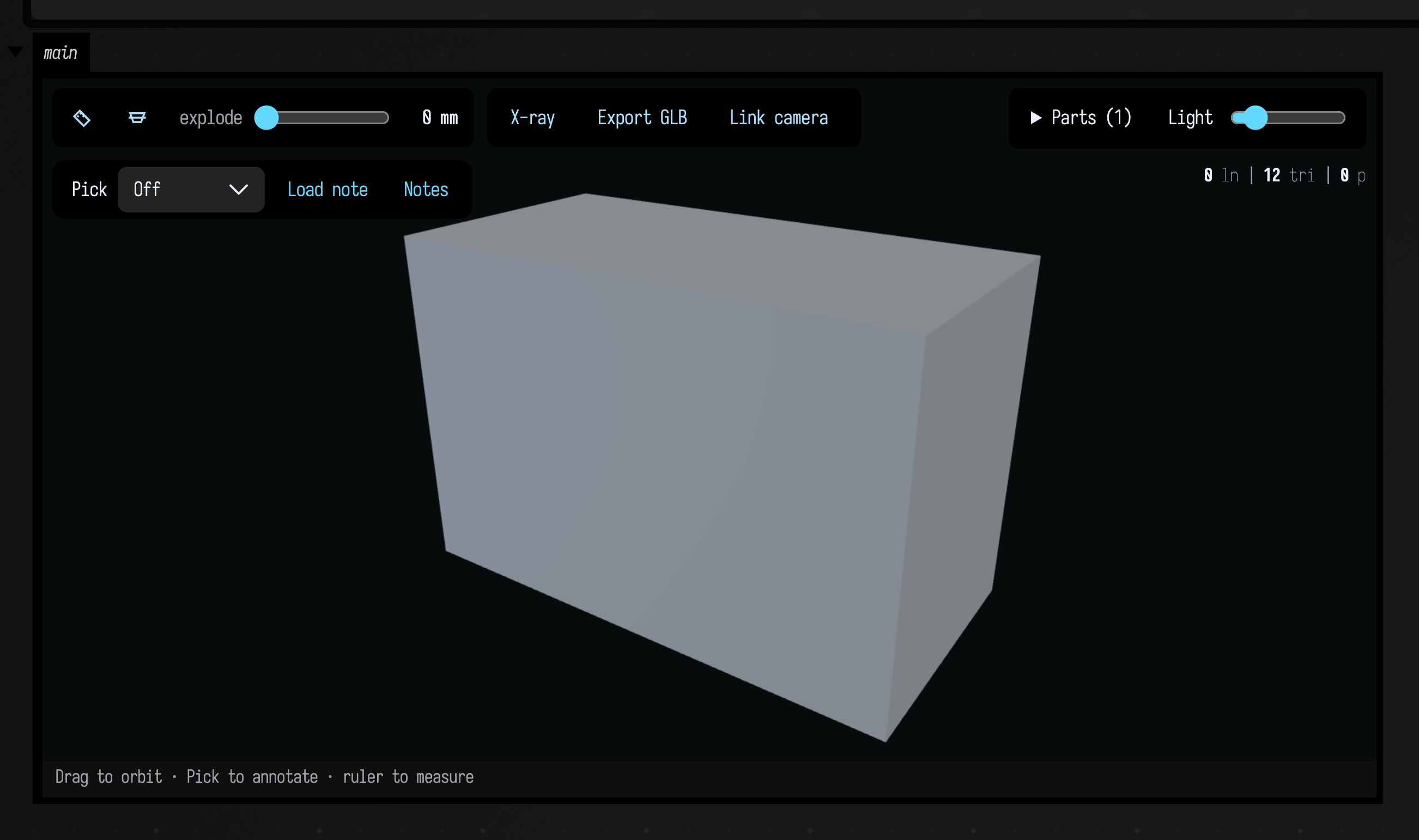
Run this complete example in a Field box. Drag to orbit, scroll to zoom, or choose Pick to select a surface feature and leave a note. The ruler measures the geometry in millimetres because that is the unit used for this block's dimensions.
:::static
val block = boxMesh(120, 80, 60)

val view = three(name = "foo", width = 760, height = 440) {
    mesh(block, id = "block", wireframe = false, pickable = true, group = 0)
    camera(yaw = 34.0, pitch = 24.0)
    background("#080b0c")
    caption("Drag to orbit · Pick to annotate · ruler to measure")
    inspect(units = "mm", groups = ["Block"])
}
three is a function on the current Field box. The block has a ThreeSceneBuilder receiver:
mesh, lines, camera and the other operations below describe the scene. The graphics and
mesh APIs are imported in ordinary Field boxes; in Kotlin source, import afield.graphics.three.*
and afield.geometry.mesh.* and call three on a Box.
Viewer name, channel and size
These are the arguments three itself takes:
Argument to three |
Meaning |
|---|---|
name = "foo" |
A stable viewer name within this box. The view ID is the box ID followed by _foo. Defaults to "three". |
channel = "main" |
The output disclosure in Field. Use distinct channels to keep two outputs visible at once. |
width = 760, height = 440 |
Frame size in pixels. Width is optional; height defaults to 430. |
samplesPerCubic = 48 |
How finely to sample FLine cubic curves. Does not change mesh triangles. |
Running the same box with the same name updates the same viewer. To keep two independent
scenes, give them different names and channels. channel alone does not give a scene a new
identity. A viewer's ID belongs to its document, so a box copied into another document gets a
scene of its own. The value returned by three is the live ThreeGeometryViewState; view.uid
is the ID the standalone viewer and the agent tools use. Take it from there rather than building
one from a box ID and name.
A scene, not a picture
The block describes what belongs in the scene. three returns a live ThreeGeometryViewState,
so you can keep changing the view after it appears. Here are the operations you can use in the
block:
| in the block | what it does |
|---|---|
mesh(m, …) |
add a TriMesh; open surfaces are supported too. Appearance and interaction options are listed below |
lines(…) — a Collection<FLine> or a vararg |
add FLines, with every behaviour they have in threeLines: picking, hover, fills, click callbacks |
camera(yaw, pitch, distance, fieldOfView) |
where the camera starts. Setting it turns auto-framing off — you picked an angle, keep it |
camera(view: MeshView) |
the same, from a MeshView you already have. The migration path for an existing figure |
panel(title, caption, facts, camera, bounds) |
one titled viewport. Call it once per panel, in order |
columns(n) |
panels per row |
title(text) / caption(text) |
shorthand for a one-panel scene |
background(css) |
scene background as a CSS colour |
helpers(on) |
the reference grid and the axis tripod |
inspect(units, decimals, …) |
enable measurement, section and explode controls; optionally supply groups, dimensions and assembly motions |
helpers is the one default that depends on what is in the scene: the grid and the tripod are on
for an FLine-only scene and off as soon as there is a mesh. Both are a fixed world size, a
10-unit grid and a 0.9-unit tripod, and a mesh is whatever size its file says it is. The toy car in
Geometry from disk is 7 cm across, so the grid would be 140 times its width
and the tripod would swallow it whole.
Mesh appearance and interaction
Each call to mesh adds one mesh to the scene. Position it by transforming the TriMesh before
adding it, for example mesh(boxMesh().translated(2.0, 0.0, 0.0)).
mesh argument |
Default | What it controls |
|---|---|---|
label |
none | A readable label for the mesh. |
wireframe |
true |
Draw every triangle edge over the shaded surface. Use false for an uncluttered surface. |
cullBackFaces |
true |
Hide the back of each triangle. Set false to see both sides of an open surface. |
flatShading |
false |
Use individual face normals for faceted shading. |
opacity |
1.0 |
Surface opacity, from transparent to opaque. |
panel |
0 |
Zero-based viewport index, or -1 to draw in every viewport. |
id |
empty | A stable name returned with mesh hits and geometry review references. Give distinct meshes distinct IDs. |
pickable |
false |
Allow the ruler to measure the mesh. Also enabled by a click callback or hover colour. |
onClick |
none | A Kotlin callback receiving a ThreeSurfaceHit with mesh ID and hit coordinates/indices. |
hoverColor |
none | A Vec4 highlight colour while the pointer is over the mesh. |
group |
-1 |
Index into the inspector's groups; -1 leaves it outside assembly groups. |
The Pick annotation tool works without pickable = true. That flag controls the ruler and
ordinary mesh interaction; annotation selection is a separate, visible-surface operation.
Lines and points
lines accepts FLines in the same coordinates as the meshes. An FLine can carry strokes, fills
and points; there is no separate points(...) operation inside this builder. For a point cloud,
set pointed = true and turn strokes off:
val samples = fline {
    moveTo(-1, 0, 0)
    moveTo(0, 1, 0)
    moveTo(1, 0, 0)
    pointed = true
    stroked = false
    pointSize = 7.0
    color = vec(1.0, 1.0, 1.0, 1.0)
}
three(name = "samples", channel = "samples") {
    lines(samples)
    helpers(false)
}
See FLine styling for stroke, fill, point and callback properties.
Measurements, parts and notes
inspect(units = "mm", decimals = 1) adds the measurement, section and explode controls. Units
label the coordinates you supplied; they do not rescale geometry. Set pickable = true on meshes
you want to measure. measurements supplies initial ThreeMeasurement dimensions, section
supplies a ThreeSection, and explode supplies a ThreeExplode.
For a grouped assembly, pass groups = listOf("base", "lid") to inspect and assign group = 0
or group = 1 to each mesh. The FLine inspector examples
show the measurement and section types.
Every single-view scene also has Pick and Save note, including scenes without inspect.
After a manual selection or saved note arrives, view.reviews() reads it from Field. From another
box or an agent, threeGeometryReviews(viewId) reads the same inbox by ID. Notes retain the
geometry revision and camera; selecting and annotating geometry explains
points, faces, edges, vertices and visible-only rectangles.
Compare views with linked cameras
Choose Link camera in each viewer you want to compare. The newly linked view adopts the camera of an already linked view in the same Field document. Orbiting, panning and zooming either view then moves both, including when they are embedded in different boxes. Click Camera linked to return that view to independent movement.
Only the camera is shared. Visible parts, X-ray, explode, sections and selections remain local, so a detailed error view can sit beside its surrounding assembly. Linking accounts for each scene's render origin and up axis, and converts millimetres, centimetres, metres, inches and feet. Other unit labels link only to the same label. Geometry must use a shared model coordinate frame.
Linking is off when a viewer opens unless its box asks for it, and linking one view does not opt other views in. It is available for ordinary single-view scenes; contact sheets with several viewports keep their own cameras.
Turning views for a display
turntable() turns a view slowly about its up axis, for a page that people look at rather than
use. On a contact sheet every panel turns together, each about its own centre, as they do when you
drag. This sheet shows six shapes in a three-by-two grid and turns them at 15° a second:
val shapes = [
    "block" to boxMesh(1.2, 0.8, 0.6),
    "tower" to boxMesh(0.5, 1.6, 0.5),
    "slab" to boxMesh(1.6, 0.3, 0.9),
    "cone" to coneMesh(segments = 7, radius = 0.6, height = 1.2),
    "can" to cylinderMesh(segments = 6, radius = 0.5, height = 1.0),
    "ring" to torusMesh(majorSegments = 12, minorSegments = 6),
]
three(name = "sheet", width = 900, height = 560) {
    columns(3)
    shapes.forEachIndexed { i, (label, shape) ->
        mesh(shape, label = label, panel = i)
        panel(
            title = label,
            camera = ThreeCameraSpec(yawDegrees = 30.0, pitchDegrees = 20.0),
            bounds = shape.toThreeBounds(),
        )
    }
    turntable(degreesPerSecond = 15.0)
}
A positive rate turns the models counter-clockwise seen from above; the default is 6° a second.
Pressing, scrolling or typing in the view pauses the turn, and it resumes resumeAfterSeconds
(2 by default) after the last interaction, from wherever you left it. A view turns only while it is
on screen and the page is visible, and draws no frames while it is still. Each panel is framed for
every angle of the turn, so nothing swings out of its cell, and a turning sheet sits a little
further back than a still one.
Views in separate outputs or boxes can turn together too. linkCamera() opens a view with
Link camera already on, so this box's two outputs share one camera and one turn:
val buildings = mapOf(
    "tower" to boxMesh(60, 140, 60),
    "barn" to boxMesh(140, 70, 90),
)
buildings.forEach { (name, building) ->
    three(channel = name, name = name, width = 360, height = 300) {
        mesh(building, wireframe = false)
        camera(yaw = 30.0, pitch = 20.0)
        linkCamera()
        turntable(degreesPerSecond = 12.0)
    }
}
linkCamera() joins the same link as the button, so a view linked from code moves with one linked
by hand, and the button still unlinks it. Running the box again does not relink a view somebody
unlinked. linkCamera(group = "north") links only with views that name the same group, so one
document can hold several separate linked sets. Moving any linked view pauses the turn in all of
them. When several linked views ask to turn, one of them drives and the link carries its camera to
the others; if that view scrolls away or closes, another takes over. A contact sheet cannot join a
link, because its panels already share one camera.
See through surfaces
Press X-ray in the viewer toolbar to reveal geometry behind filled surfaces. The
Surface slider sets their opacity. Edges draw after the translucent faces, with
slightly stronger stroke opacity, so the structure stays legible. Points keep their original contrast.
This works in ordinary three { … } scenes without inspect. Turn it off to restore
the original surface appearance. It changes the view only: no geometry is cut or moved.
Picking still stops at the nearest surface, including in X-ray mode. Hide a part or use a section cut when you want to select geometry behind it. Saved notes and their images retain the X-ray setting and opacity, so a reviewer sees the same context.
Export a GLB
Press Export GLB to download the visible geometry as a binary glTF file. The export keeps colors, part names, hidden-part choices and the current exploded or insertion positions. With X-ray enabled, surfaces carry the selected opacity in their materials; strokes retain their stronger opacity. Turn X-ray off before exporting an opaque model. Section cuts are baked into the exported surfaces and lines, without adding caps.
Meshes, lines and points all travel in the file. Viewer controls, selection markers,
measurement labels and the helper grid do not. This is a snapshot of the displayed
geometry, rather than a fabrication solid or an animation. Other applications choose
their own lighting and transparency sorting; line widths and point sizes also depend on
the receiving viewer. Inspector units mm, cm, m, in and ft convert to glTF metres.
An unspecified or other unit label leaves coordinates unchanged, with the label retained
in the scene metadata.
With gltfpack installed, Export GLB compresses the file before it downloads, and the status
line shows both sizes. gltfpack quantizes the buffers and meshopt-compresses them, keeping node and
material names. It is optional: pick gltfpack in ./field.sh --setup, or run
./gradlew prepareGltfpack, which fetches a pinned, checksummed build. Without it the export stays
uncompressed. Box code can use the same tool through Gltfpack.compress(bytes). A compressed file
uses EXT_meshopt_compression, which three.js, Blender 4.2 and later, and most web viewers read.
A studio look
studio() gives a model a more atmospheric presentation: ACES tone mapping, a soft-shadowed key
light, sky fill, a cool rim light, ambient occlusion and a dark ground with a faint grid. Give the
mesh a material to go with it:
:::fold a revolved vase
// A vase: a profile of radius against height, revolved around y.
val vase = revolveMesh(
    (0..40).map { i ->
        val y = -1.25 + i / 40.0 * 2.5
        vec(0.45 + 0.3 * sin(i / 40.0 * 5.0) + 0.15 * (i / 40.0), y)
    },
    RevolveAxis.Y,
    segments = 64,
)

:::endfold

// The same vase with no look, then with studio().
three(name = "plain", channel = "plain", width = 560, height = 420) {
    mesh(vase, wireframe = false, cullBackFaces = false)
    camera(pitch = 22.0, padding = 1.6)
    background("#060807")
}
three(name = "studio", channel = "studio", width = 560, height = 420) {
    mesh(
        vase,
        wireframe = false,
        cullBackFaces = false,
        material = ThreeSurfaceMaterial(roughness = 0.4f, metalness = 0.6f),
    )
    studio(groundY = -1.25)
    camera(pitch = 22.0, padding = 1.6)
    background("#060807")
}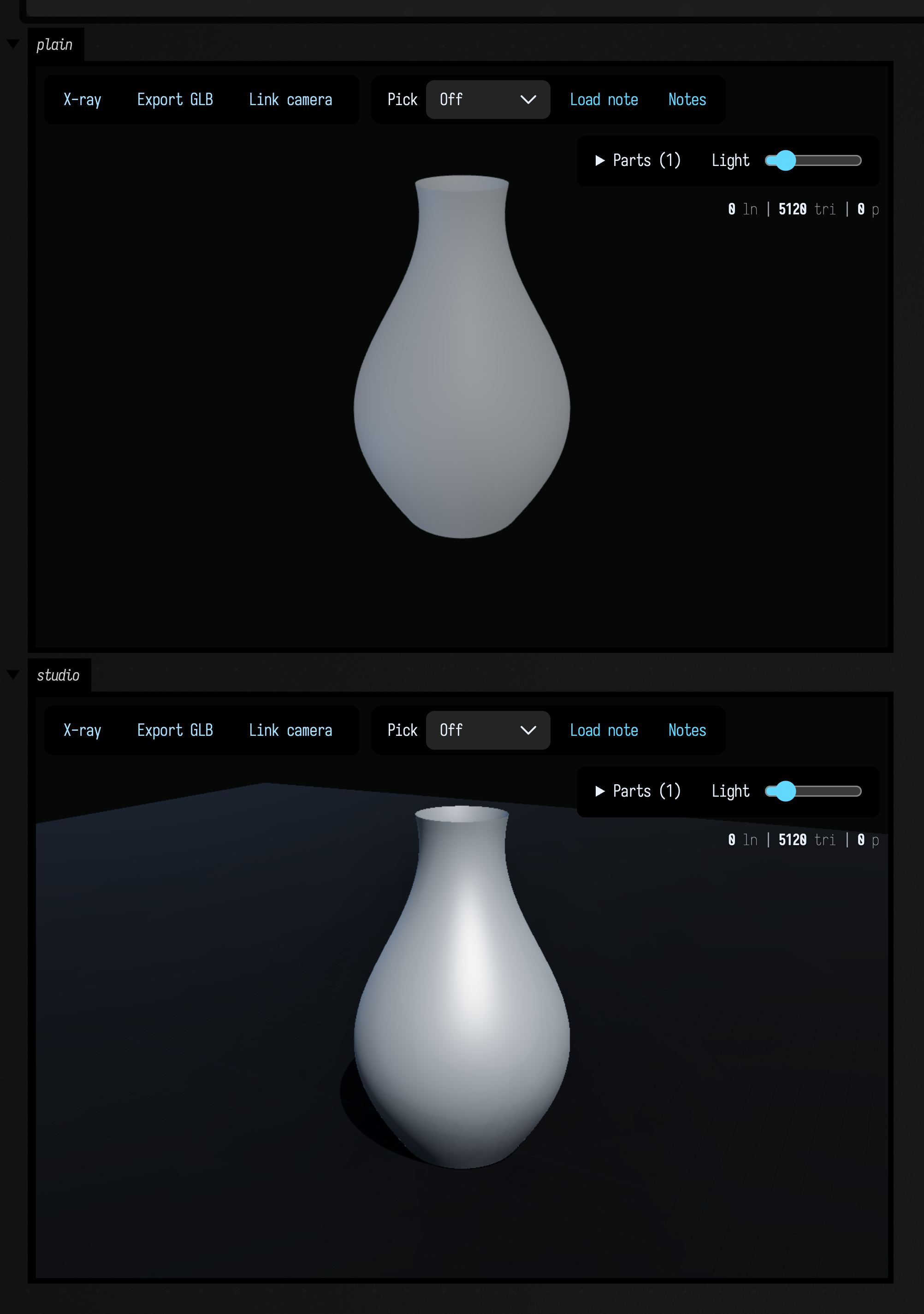
studio() switches off the reference grid and axis tripod. Ambient occlusion draws in a single
view. A contact sheet and X-ray draw without it, and studio(ambientOcclusion = false) turns it off.
geometry { } uses this look for its models; see the madp_geometry starting point.
One scene, two kinds of thing
A gyroid marched inside a finite box is an open surface. Where it reaches the edge of the
sampling window, it leaves boundary loops. Those loops can be hard to see on a shaded surface, so
this example draws them as lines over the mesh using toFLines(MeshLines.BOUNDARY).
:::static
/*
A gyroid is a triply-periodic minimal surface. Marched inside a finite box it is OPEN: the
surface leaves the sampling window rather than closing inside it, and every place it does that
is a boundary loop. `open(20)` in the printed summary is the claim; the picture is the evidence.
*/
val surface = marchingCubes(sdfGyroid(4.0, 0.3), boundsAround(radius = 1.0), 72)
println(surface.summary())

// The rim, as FLines, in the mesh's own coordinates. One closed ring per hole.
val rims =
    surface.toFLines(MeshLines.BOUNDARY).map { ring ->
        ring.color = vec(1.0, 0.45, 0.12, 1.0)
        ring.thickness = 2.6
        ring
    }
println("open boundary loops: " + rims.size)

three(channel = "gyroid", height = 470, width = 760) {
    mesh(surface, wireframe = false)
    lines(rims)
    camera(yaw = 32.0, pitch = 20.0, padding = 1.02)
    title("marched gyroid, with its " + rims.size + " open boundary loops drawn in the same scene")
    caption("the solid and the annotation are one scene in model space, so orbiting moves both")
}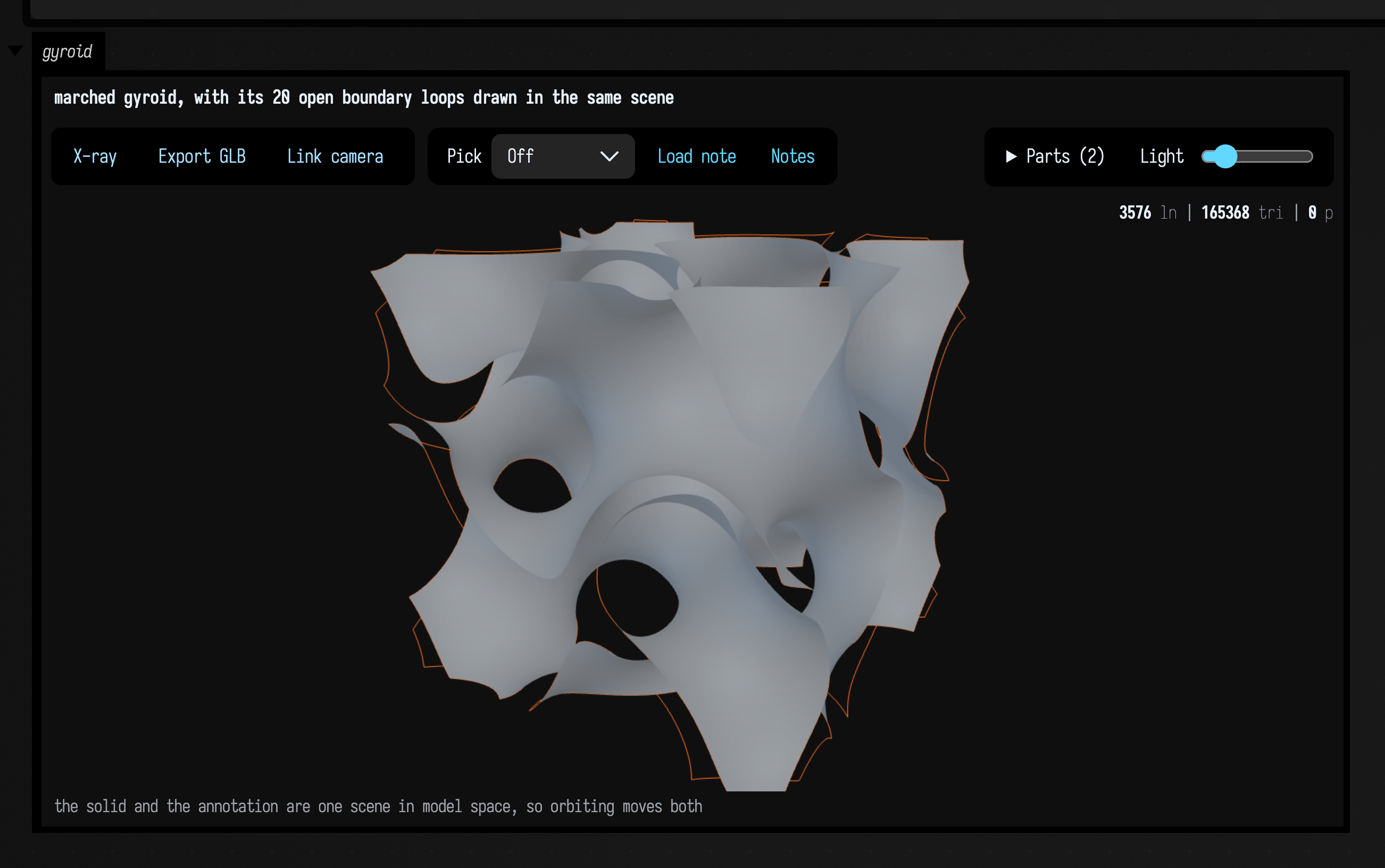
The HUD in the top right counts the whole scene, lines and triangles together:
3576 ln | 165368 tri | 0 p.
three { lines(…) } uses the same builder as threeLines(...), so FLines behave identically in
both, including picking and click callbacks. A mesh reaches the viewer through
TriMesh.toThreeDrawable(), which turns it into a ThreeDrawable: geometry plus how to draw it.
A wide viewer can keep its controls compact with controlGroup("controls", columns = 2) { ... }.
The control surface uses up to two columns and collapses to one in a narrow output. The ordinary
controlGroup("controls") { ... } retains its single column; changing layout preserves control
identities, cached values and callbacks.
When the geometry updates and the camera preset has not changed, the view keeps whatever orbit, pan and zoom you had. Changing the preset starts a new view. Resizing a view also keeps your position.
The camera
ThreeCameraSpec has the same fields as MeshView and VisionGeometryPreview.Camera, the
CPU rasterizer's camera:
yawDegrees— orbit around+y.0looks straight down \( -z \).pitchDegrees— lift above the horizon. Positive looks down on the geometry.distance— in multiples of the bounding-sphere radius, so one spec frames a 2 cm mesh and a 2 m one. The rasterizer uses it; the viewer zooms to fit instead.padding— the viewer's margin around the shape's outline when it zooms to fit:1.0touches the frame's edges, the default1.06leaves a little air. The rasterizer ignores it.fieldOfViewDegrees— vertical. Smaller is a longer lens and less perspective.
The names and meanings match, so one camera can be handed to either renderer.
Contact sheets
For a custom contact sheet, panel(...) declares viewports in order, and a mesh(...) goes into
the panel declared most recently, or the one panel = n names. FLine content is shared between viewports. This example builds a sheet by
hand:
val cube = boxMesh()
three(name = "comparison", channel = "comparison", width = 760, height = 320) {
    columns(2)
    mesh(cube, panel = 0, wireframe = true)
    mesh(cube, panel = 1, wireframe = false)
    panel(title = "Triangles", bounds = cube.toThreeBounds())
    panel(title = "Surface", bounds = cube.toThreeBounds())
}
threeGrid and threeTurntable below build common layouts for you. Pick and Save note work on a
sheet: a pick uses the panel under the pointer, and the note remembers that panel, so loading it
selects the feature there again and its images are of that panel. Rectangle needs a single viewport.
One WebGL context, several panels
Drag to orbit; use the mouse wheel, trackpad scroll, or middle-button drag to dolly in and out. Multi-panel views retain your orbit and dolly across geometry and selection updates. Dolly moves the camera relative to its fitted starting view, so close inspection can crop the object.
All the panels of a contact sheet share one viewer and one WebGL context. Separate viewers would
each need their own context, and Chrome keeps only around sixteen alive, silently blanking the
oldest with nothing in the console. Two galleries of nine would already be too many. A
ThreePanel is a viewport within the one viewer, which is also much faster.
threeGrid — several meshes, each framing its own bounds
This example lays four unrelated shapes out in a two-by-two sheet, with a fact line under each:
:::static
/*
Four unrelated shapes. Each panel frames its OWN bounds, so the small one is not lost beside the
large one — that is the difference between a grid and a turntable, and only the Kotlin side knows
which of the two it is building.
*/
val ball = marchingCubes(sdfSphere(1.0), boundsAround(radius = 1.3), 40)
val drilled = marchingCubes(sdfSubtract(sdfSphere(1.0), sdfCylinder(0.34, 4.0)), boundsAround(radius = 1.3), 64)
val twisted = marchingCubes(sdfBox(vec(1.2, 1.8, 0.4)).twisted(0.35), boundsAround(radius = 1.2), 72)
val ring = torusMesh(64, 32, 0.62, 0.24)

threeGrid(
    "marched sphere, resolution 40" to ball,
    "…drilled through: the drill added a handle" to drilled,
    "sdfBox(…).twisted(0.35)" to twisted,
    "torusMesh(64, 32) — genus 1 by construction" to ring,
    columns = 2,
    facts = true,
    cellWidth = 430,
    height = 760,
    channel = "grid",
    view = MeshView(pitchDegrees = 44.0),
)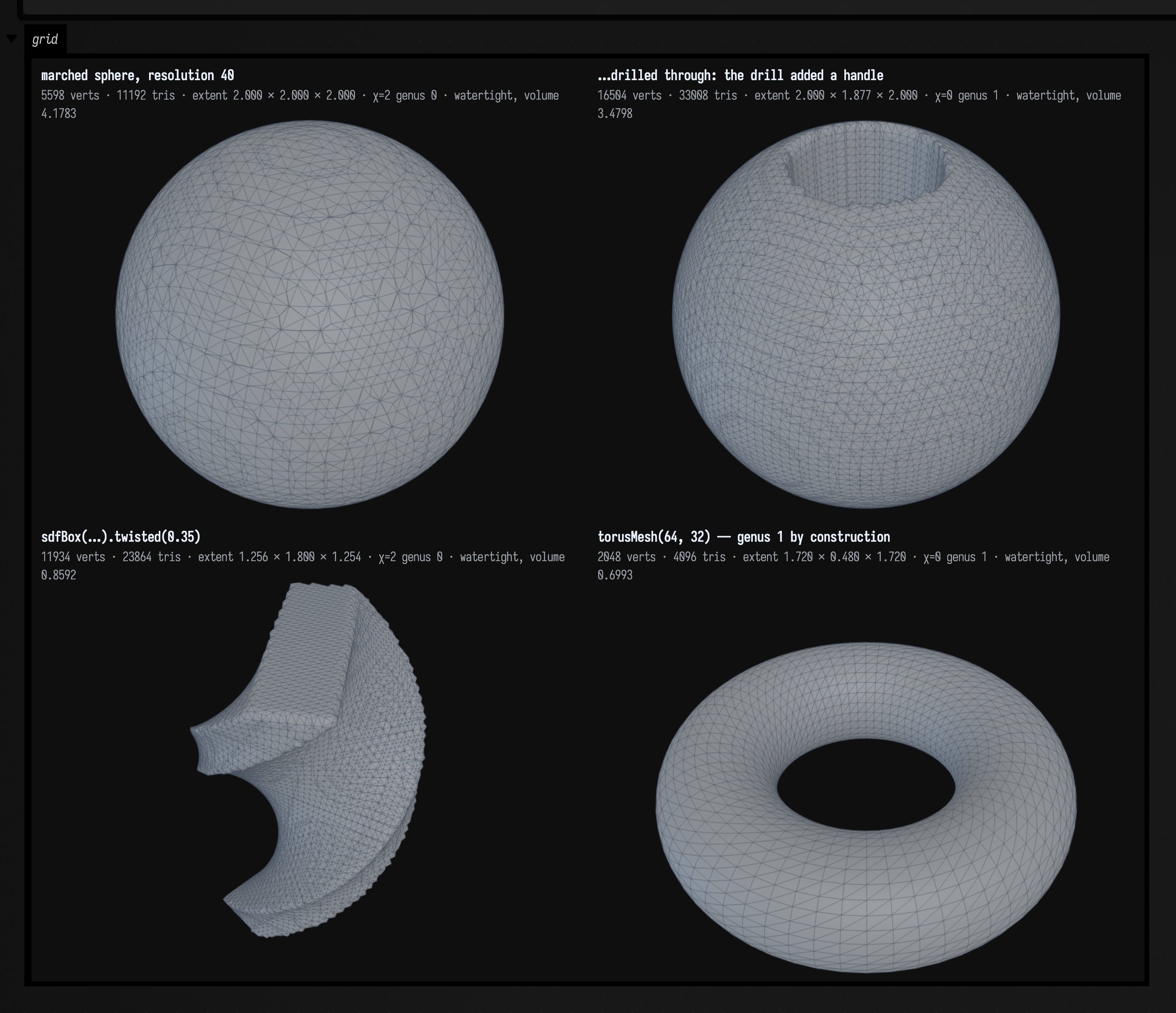
Each panel has its own camera, and carries the fact line TriMesh.threeFacts() computes, the
same line toFigureHtml writes under a rasterized figure.
showMeshGrid prints the fact line by default and forwards facts to threeGrid; threeGrid
called directly leaves it off unless asked, as above. For a gallery that has something specific to
say about each cell, use the List<ThreeMeshPanel> overload:
threeGrid(
    [
        ThreeMeshPanel("cuboctahedron", solid, facts = "12 vertices · 24 edges · 14 faces (8 triangles, 6 squares)"),
        ThreeMeshPanel("…kis'd", kissed, facts = "38 vertices · 84 edges · 48 faces (all triangles)"),
    ],
    columns = 2,
)
threeTurntable — one mesh, several angles, one upload
This example shows one twisted box from four angles in a row:
:::static
// One mesh, four angles, ONE upload and ONE WebGL context. Every panel frames the SAME bounds, so
// the shape does not appear to breathe as it turns.
val twisted = marchingCubes(sdfBox(vec(1.2, 1.8, 0.4)).twisted(0.35), boundsAround(radius = 1.2), 80)
println(twisted.summary())
threeTurntable(twisted, channel = "turntable", height = 290)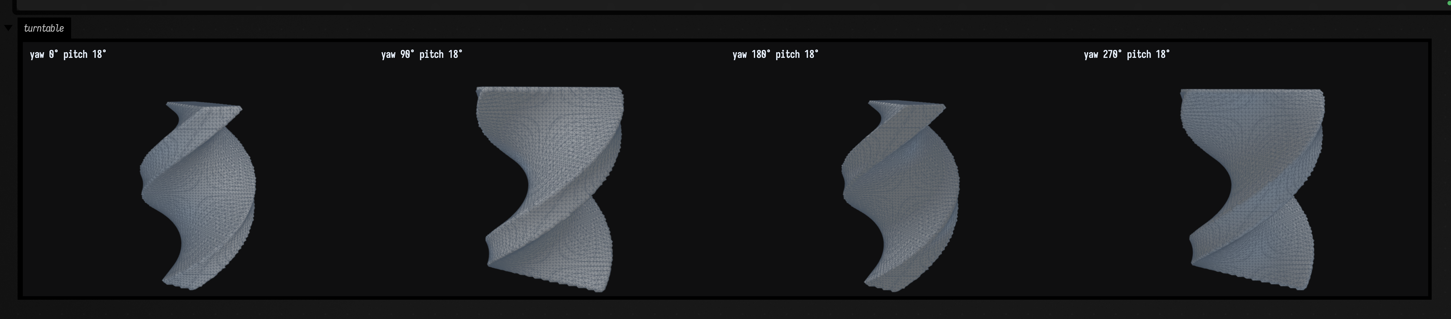
At yaw 0° and 180° this solid is a narrow crescent, and at 90° and 270° it is a broad S; any single view would leave you guessing at its shape.
Unlike a grid, the turntable:
- adds the mesh once with
panel = -1, meaning every panel, so a large mesh is uploaded once and drawn from each angle; - gives every panel the same
bounds, so the shape does not appear to grow and shrink as it rotates. A grid frames each panel on its own bounds.
showMesh and the renderer parameter
Every entry in the showMesh family takes a renderer, and the default is the Three.js viewer.
| you call | you get |
|---|---|
showMesh(mesh) |
Opens the orbitable Three.js viewer, equivalent to three(subject = mesh). This is the default for mesh display. |
showMesh(mesh, renderer = MeshRenderer.CPU) |
Produces a static CPU-rasterized figure at a fixed camera. Use it when you need a deterministic image without WebGL. |
showMeshGrid(…) |
Delegates to threeGrid to compare meshes in interactive viewports. Each subject retains a distinct panel. |
showMeshTurntable(…) |
Delegates to threeTurntable for views around a subject. It helps reveal shape hidden from a single angle. |
showMeshDiagnosis(mesh) |
Always uses the CPU rasterizer for its diagnostic figure. It has no renderer-selection parameter. |
mesh as the last expression in a box (the inline card) |
Uses the CPU rasterizer for the inline value card. Call showMesh explicitly when you want an orbitable view. |
MeshView.width and MeshView.height size the figure on both paths: the raster on the CPU path,
the iframe on the GPU path. Pass height to showMesh only to make the Three.js iframe a different
height from the view.
Give the width in pixels. The output panel sizes itself from the iframe's pixel width, and a percentage leaves the panel at whatever width it already had. That suits an FLine viewer filling its column, but a wide gallery collapses to the panel's width and loses the right-hand part of every picture. Output panel sizing explains the rules.
Which renderer draws this
Field has more ways to put geometry on a screen than the viewer and the rasterizer. This table lists them all, and what each is for:
| path | what it draws | where the pixels are made | reach for it when |
|---|---|---|---|
three, threeGrid, threeTurntable, threeLines, threeInspect — afield/graphics/three/Three.kt, ThreeJsViewer.kt |
FLines and TriMeshes together, in 3D |
WebGL (three.js r184, vendored) in a /threejs iframe inside the box output |
you want to turn it; you want a solid and its annotations in one scene. The default for the whole showMesh family |
renderPng, renderPixels, toFigureHtml, toHTML, showMeshDiagnosis, MeshRenderer.CPU — afield/graphics/visionos/VisionGeometryPreview.kt |
one TriMesh, fixed camera, still |
CPU z-buffer in the JVM, AWT-free, encoded by PngEncoder |
you need the same pixels twice (see below); there is no WebGL context to spare; you want a pixel buffer to composite by hand |
lines, l, drawToSVG, inspect — afield/ui/visualization/someSkiko.kt |
FLines, 2D only | SVG text emitted by a Skia recording canvas; the browser rasterizes it | 2D figures: crisp at any zoom, tiny payload, headless-safe |
lines(editable = true), and the automatic upgrade when an FLine has onClick or hoverColor — FLineEditableSvg.kt |
the same, plus click / hover / drag / freehand | SVG in the browser, plus a server-side edit session | direct manipulation of control points; a figure you can click to name |
moduleHere, Renderer, RenderToTexture, and StandardRenderer / Fabricate on top of them — afield/four/ |
arbitrary real-time scenes, Gaussian splats, hardware ray tracing | Vulkan on the desktop GPU, in a GLFW window (offscreen targets still need the window) | real-time work, hot-reloaded shaders, hundreds of thousands of primitives, OpenXR |
visionMetal — afield/graphics/visionos/VisionMetal.kt |
your live Metal shader plus its geometry | Metal, on the Vision Pro | headset live-coding (Apple Vision Pro, geometry in the headset). Its desktop stand-in is previewVisionGeometry, which is the CPU rasterizer again |
the visionOS native FLine viewer — native/field-visionos/Field4Vision/FLine/ |
whatever threeLines / three published |
RealityKit / Metal on the headset | you want an existing 3D figure in the volume (Apple Vision Pro). It subscribes to the same __threejs__ channel; there is no second API |
remoteAr — afield/ui/output/outputs.kt, afield/lang/remotejs/RemoteArKotlinJs.kt |
your Kotlin, compiled to JS, in a WebXR page | WebGL in the browser or headset | AR/VR where the code runs in the head rather than on the desktop (RemoteJS and WebXR) |
rasterizeFLines, Img, showImg, rasterizeText, heatmapImage, RectSLFitFigure |
2D marks into a pixel buffer, no projection and no depth | CPU in the JVM, PngEncoder |
measurement rasters, image pipelines, figures that have to be identical in a test |
Two entries in that table are commonly misread:
Box.lines(...) draws in 2D. Given a 3D FLine, it uses x and y for an orthographic view
down \( -z \), with no depth sorting or hidden-line removal. The z coordinate is retained for
picking, so a click can still report the 3D position. For perspective, project first with
FLine.byPerspectiveProjecting(...) or use threeLines.
The ray tracer is not a separate renderer. Ray tracing examples is
VK_KHR_ray_tracing_pipeline inside Field 4, and Fabricate's StandardRenderer is a deferred
g-buffer / shadow / AO / composite stack built on the same primitives. One Vulkan renderer, three
front ends.
What the CPU rasterizer is for
The CPU rasterizer is useful in a few situations:
It is deterministic. The same input gives the same pixels every time, whatever the GPU, driver or antialiasing. Use it when a test or a comparison needs the same number twice.
It needs no WebGL context. The inline card that appears when a box ends on a TriMesh uses it,
so a list of meshes does not run into the browser's limit on WebGL contexts.
It renders into a pixel buffer. TriMesh.renderPixels hands you ARGB ints and a size, for
compositing several meshes into one figure yourself.
Why it writes its own PNGs
VisionGeometryPreview avoids java.awt: touching AWT inside Field's server JVM on macOS
initialises AppKit in a process whose main thread belongs to GLFW, and the process dies
silently.
The same mesh, both ways
This example draws one marched solid twice, with the same MeshView, once on each renderer:
:::static
// The same mesh, the same MeshView, the same frame size — both renderers. What changed is easiest
// to see with the two side by side.
val solid = marchingCubes(
    sdfSmoothUnion(sdfSphere(0.78), sdfBox(vec(2.1, 0.32, 0.32)), k = 0.28),
    boundsAround(radius = 1.35),
    64,
)
val view = MeshView(width = 520, height = 400, wireframe = true)

showMesh(
    solid,
    channel = "three.js — the default",
    view = view,
    height = view.height,
    renderer = MeshRenderer.GPU,
    title = "MeshRenderer.GPU — MeshStandardMaterial, orbitable",
)
showMesh(
    solid,
    channel = "the CPU rasterizer",
    view = view,
    renderer = MeshRenderer.CPU,
    title = "MeshRenderer.CPU — two-light lambert, deterministic, still",
)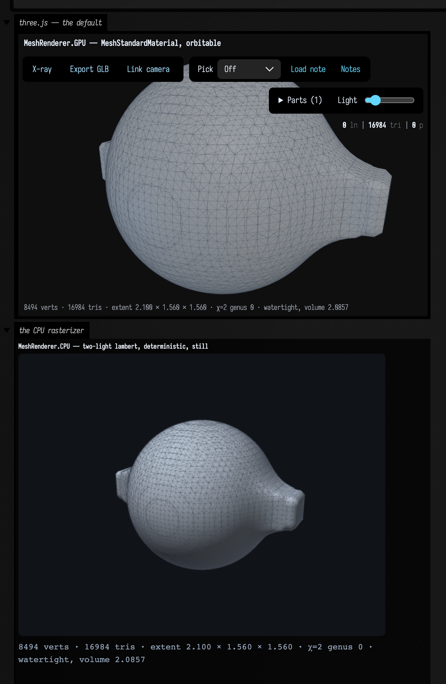
The same mesh, MeshView and 520 × 400 frame give two visibly different pictures:
- Shading differs, and is not meant to match. The rasterizer is a simple two-light Lambert
model over the vertex colours. The viewer is three.js's
MeshStandardMaterialunder an ambient, key and rim light. - Framing differs: the rasterizer places the eye at
distance; the viewer zooms to fit withpadding. - The input is the same. Both renderers compute missing normals with
shadedNormalsat a 35° crease angle, so hard edges stay hard, and both useTriMesh.colorsor the same default grey. - Back-face culling is the same, which matters for diagnosis; the next section shows it.
- The fact line is the same.
Back-face culling, on both renderers
A face wound the wrong way is missing in the rasterizer, not dark, and the
polytope and typography pages both use that as a
winding test. ThreeDrawStyle.surface(cullBackFaces = true) is the default in the viewer as well,
so it is missing there too. This example reverses a band of a sphere's triangles:
:::static
// Take a sphere and reverse the winding of one band of triangles. Not one vertex moves.
val ball = icosphereMesh(3, 0.8)
val idx = ball.indices.copyOf()
var reversed = 0
for (t in 0 until ball.triangleCount) {
    val cy = (ball.position(ball.ia(t)).y + ball.position(ball.ib(t)).y + ball.position(ball.ic(t)).y) / 3.0
    if (cy > 0.30) {
        val b = idx[t * 3 + 1]
        idx[t * 3 + 1] = idx[t * 3 + 2]
        idx[t * 3 + 2] = b
        reversed++
    }
}
val holed = TriMesh(ball.positions.copyOf(), idx)

println("reversed %d of %d triangles; not one vertex moved".format(reversed, ball.triangleCount))
println("volume  %.4f  ->  %.4f".format(ball.signedVolume(), holed.signedVolume()))
println("consistently oriented: " + holed.topology().isConsistentlyOriented)

val view = MeshView(width = 460, height = 380, yawDegrees = 18.0, pitchDegrees = 38.0, wireframe = true)
showMesh(
    holed,
    channel = "three.js",
    view = view,
    height = view.height,
    renderer = MeshRenderer.GPU,
    title = "the band is GONE, not dark",
)
showMesh(
    holed,
    channel = "the CPU rasterizer",
    view = view,
    renderer = MeshRenderer.CPU,
    title = "…and gone here too, which is the whole point",
)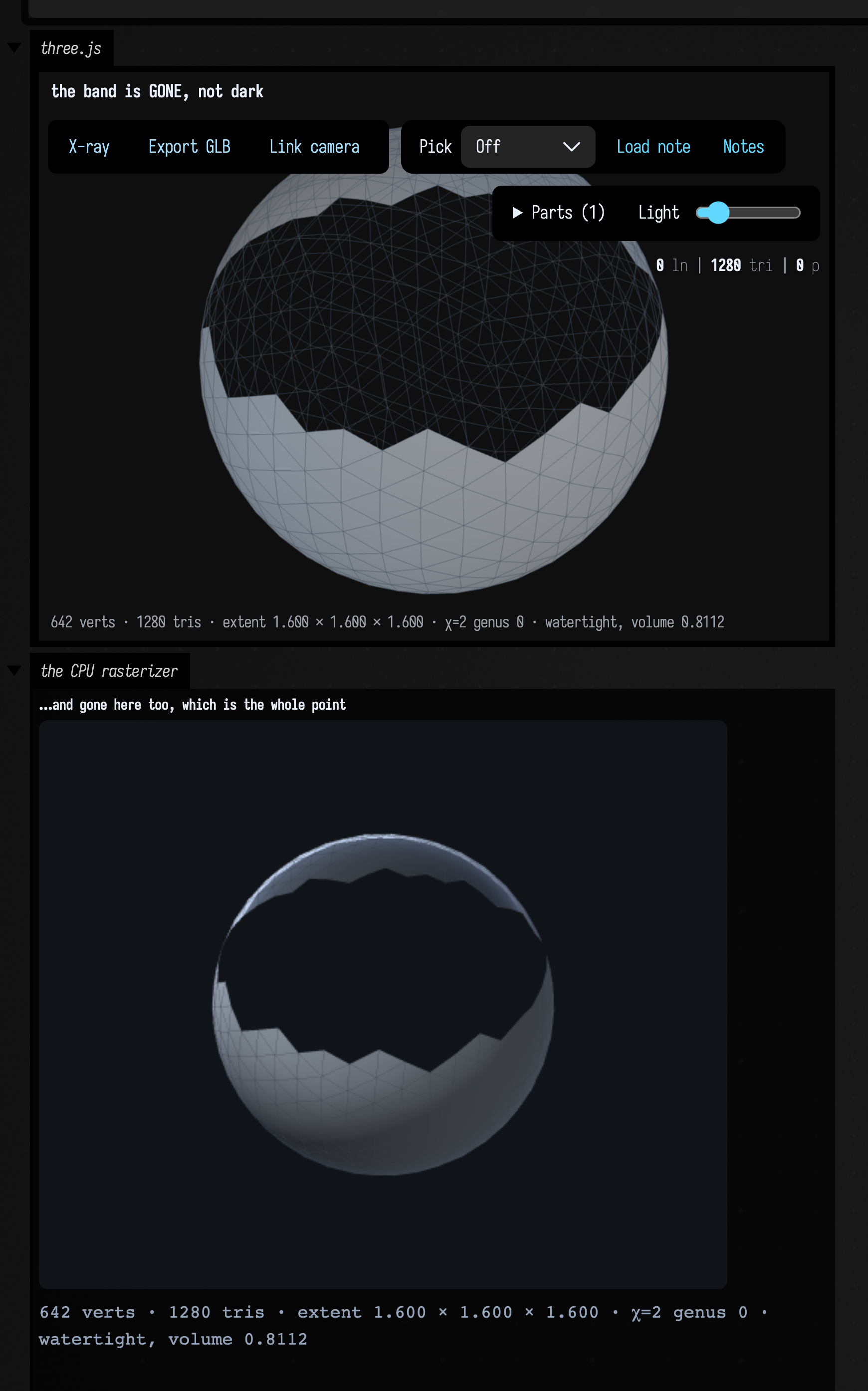
394 of 1280 triangles are reversed and no vertex has moved, and both renderers show the same hole. The numbers:
signedVolume()goes from 2.1262 to 0.8112, which is wrong, with nothing to flag it.- the fact line still reads
χ=2 genus 0 · watertight: χ counts vertices, edges and faces, and reversing a triangle changes none of them. topology().isConsistentlyOrientedisfalse, and is the check to use.fixWinding()repairs the mesh.
The overlays differ: in the Three.js panel the wireframe overlay is not back-face culled, so you can still see the reversed triangles' edges drawn across the hole. The rasterizer's depth-tested wireframe is culled with its surface, so its hole is bare. The surfaces agree.
Measuring and sectioning a solid
inspect(...) inside a three { } scene, and
Box.threeInspect(...) for lines alone, add a measurement tool, a section plane with a real cut
outline, and an explode scrubber; the tools themselves are documented, with figures, in
FLine examples.
A mesh is not pickable by default, because a solid filling the frame would sit in front of every
annotation it was drawn to explain. Ask for it with mesh(car, pickable = true), or let an
onClick or a hoverColor imply it, and pair that with inspect(...) on the same scene: the flag
is what lets the ray find the solid and the toolbar is what draws the dimension. A hit arrives as a
ThreeSurfaceHit, resolved to a vertex, an edge or a triangle, so a dimension can run from a corner
of the solid to an annotation beside it, as in this example:
:::static
// A block with a bore drilled down through it, and a datum line standing beside it.
val part = marchingCubes(
    sdfSubtract(sdfBox(vec(2.0, 1.2, 1.2)), sdfCylinder(0.35, 2.0)),
    boundsAround(radius = 1.3),
    72,
)
val datum = fline {
    moveTo(1.4, -0.6, 0.0)
    lineTo(1.4, 0.6, 0.0)
    color = vec(1.0, 0.55, 0.2, 1.0)
    thickness = 2.5
}

three(name = "section", channel = "section", width = 760, height = 460) {
    mesh(part, id = "part", wireframe = false, pickable = true)
    lines(datum)
    camera(yaw = 30.0, pitch = 24.0)
    inspect(
        // Cut halfway through along z, so the plane runs straight down the bore.
        section = ThreeSection(enabled = true, normal = floatArrayOf(0f, 0f, 1f), fraction = 0.5),
        // From the block's +x face, on the cut plane, to the datum beside it: 1.4 - 1.0 = 0.4.
        measurements = [
            ThreeMeasurement(
                ThreeMeasureElement.point(1.0, 0.0, 0.0),
                ThreeMeasureElement.segment(1.4, -0.6, 0.0, 1.4, 0.6, 0.0),
                "clear ",
            ),
        ],
    )
}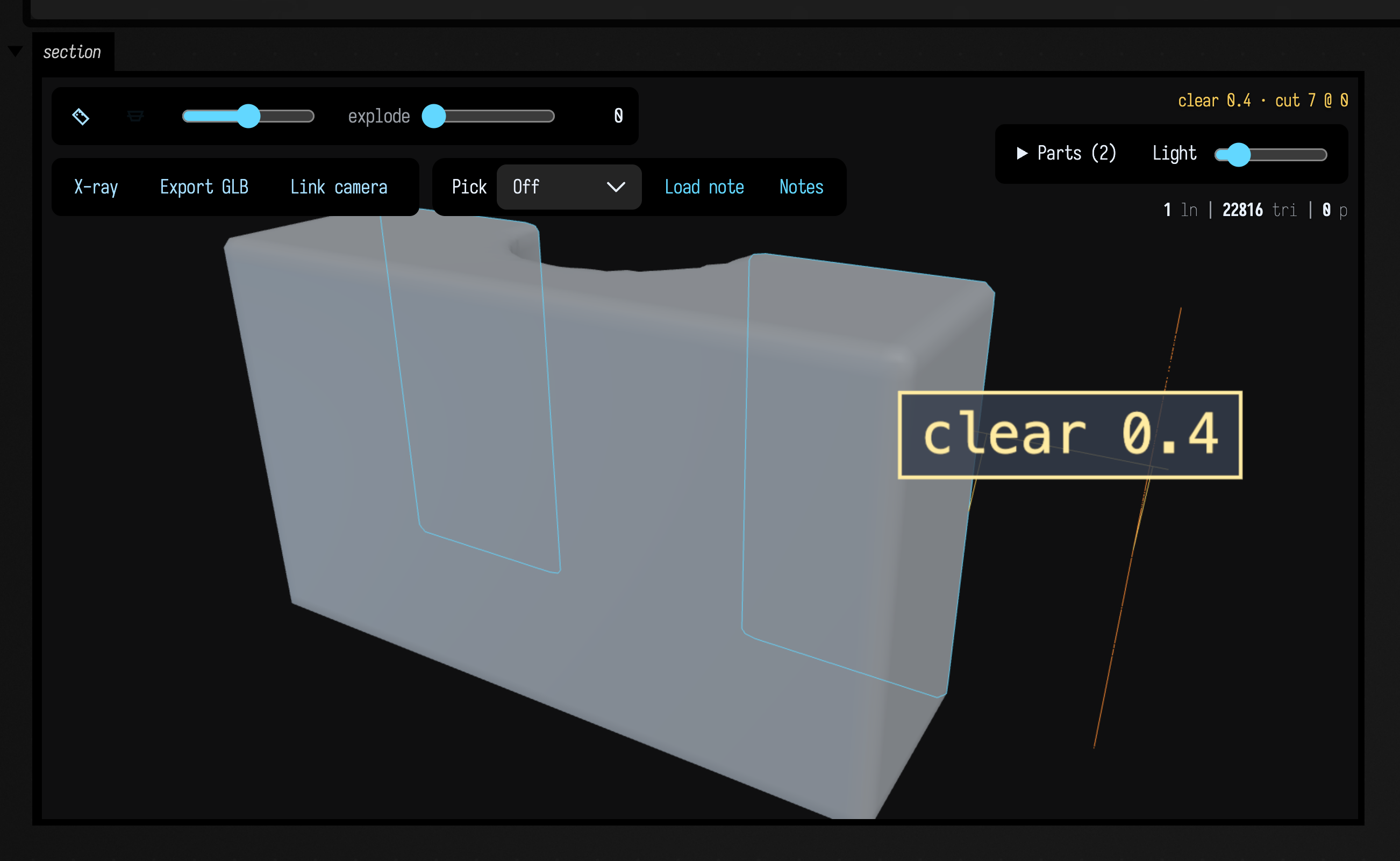
What you aim at is decided by true perpendicular distance in the hit triangle's plane, within a snap radius of 0.14 of that triangle's own longest edge, and a corner is tested before an edge. So a sliver has no clickable interior: every point of a triangle ten long and half a unit tall falls inside its own snap radius of an edge or a corner.
The section plane cuts a mesh, wireframe overlay included. The explode scrubber moves
meshes and their outlines by inspection group, along with grouped FLine geometry.
Give related objects the same group to keep them together; solidParts sets this up
for native solids. X-ray can be combined with either control.
Show a part or a group
Open Parts to browse the scene as a tree. A mesh and its outline share one checkbox when they have the same assembly group or drawable ID. Folder checkboxes show a dash when only some children are visible. Select all shows or hides the entire scene.
Shift-click a part or folder checkbox to solo it. Shift-click it again to restore the previous visibility; shift-click a different part to move the solo without losing that previous view. An ordinary click ends solo mode and edits the current visibility.
Use inspect(partPaths = …) to organise a large scene. Keys are stable mesh IDs, assembly
group names, or review feature IDs; values are lists of folder names. The final row retains
its part name. Folder labels do not change geometry IDs or invalidate annotations. For example:
three(name = "vehicle") {
    mesh(boxMesh(120, 60, 40), id = "body", wireframe = false)
    mesh(boxMesh(20, 20, 20), id = "wheel", wireframe = false)
    inspect(
        partPaths = mapOf(
            "body" to ["Vehicle", "Bodywork"],
            "wheel" to ["Vehicle", "Running gear"],
        ),
    )
}
Uncategorised meshes, interactive FLines, and batched guides have their own folders. A batched guide buffer is one selectable entry: it does not claim per-line visibility. Hidden geometry is excluded from picking and visible-scene exports, including X-ray views.
Editing a curve before an expensive operation
threeLines(curves, editable = true, width = 1000, onEditCommitted = { edited -> … })
provides the existing 3D anchor and Bézier-handle editor with a callback when a drag
finishes. The callback receives detached copies of all the displayed FLines, after
the drag's position updates. Camera movements do not call it. Select the pencil
tool to edit and the camera tool to orbit or dolly.
Keep the callback short: queue the snapshot, then validate it or rebuild dependent
geometry on your own worker. The callback does not supply undo, persistence,
constraints, or a solver; those belong to the application using the curves. Pass
the accepted curves back to threeLines under the same viewer name to display any
constraints you applied. width is optional and otherwise fills the output area.
The payload both kinds of scene share
ThreeGeometryPayload's lines / fills / points hold the FLines, and a payload with an empty
drawables list carries no mesh keys, so the editable path, the inspector and the mesh scenes above
all share one format.
A scene reaches the viewer in two parts: a small description over the websocket, and its
geometry (FLine and mesh buffers, and a solid's exact boundary) as one binary download that the
viewer fetches when it needs it. A scene's geometry may be up to 512 MB; set AFIELD_THREE_PAYLOAD_LIMIT_MB to
change that. A scene over the limit is not sent: the call that built it throws
ThreePayloadTooLargeException, which gives the size and the largest drawables, and the view keeps
what it was showing. Restyling parts with styleParts sends only the new styles, however large the
scene is.
Three.js ships with Field (src/commonMain/resources/vendor/three/0.184.0/), so the viewer works
offline.
Play with it
Open the gallery, with the five boxes
on this page and their captured outputs. Drag a 3D view to orbit it; use Parts and X-ray
to explore its geometry. Click a box to read its code. To change facts = true to false, or
set the grid's columns to 4, use Open in Field·4 and run the edited box.
Optional viewer tools
Measure, section and explode (above), X-ray (See through surfaces) and Export GLB (Export a GLB) are built into the viewer, and none of them is a tool in this sense. A tool is for anything else.
A scene can opt into a tool without making that tool part of Field. Tools are trusted ES modules served by the same Field server. The default viewer loads none. This small example adds a reference-axis toggle:
three(name = "tools-example") {
    tools("/threejs_tools_demo.js")
    lines(
        fline {
            moveTo(0.0, 0.0, 0.0)
            lineTo(2.0, 1.0, 0.0)
        },
    )
    helpers(false) // so the grid's own tripod is not mistaken for the tool's axes
}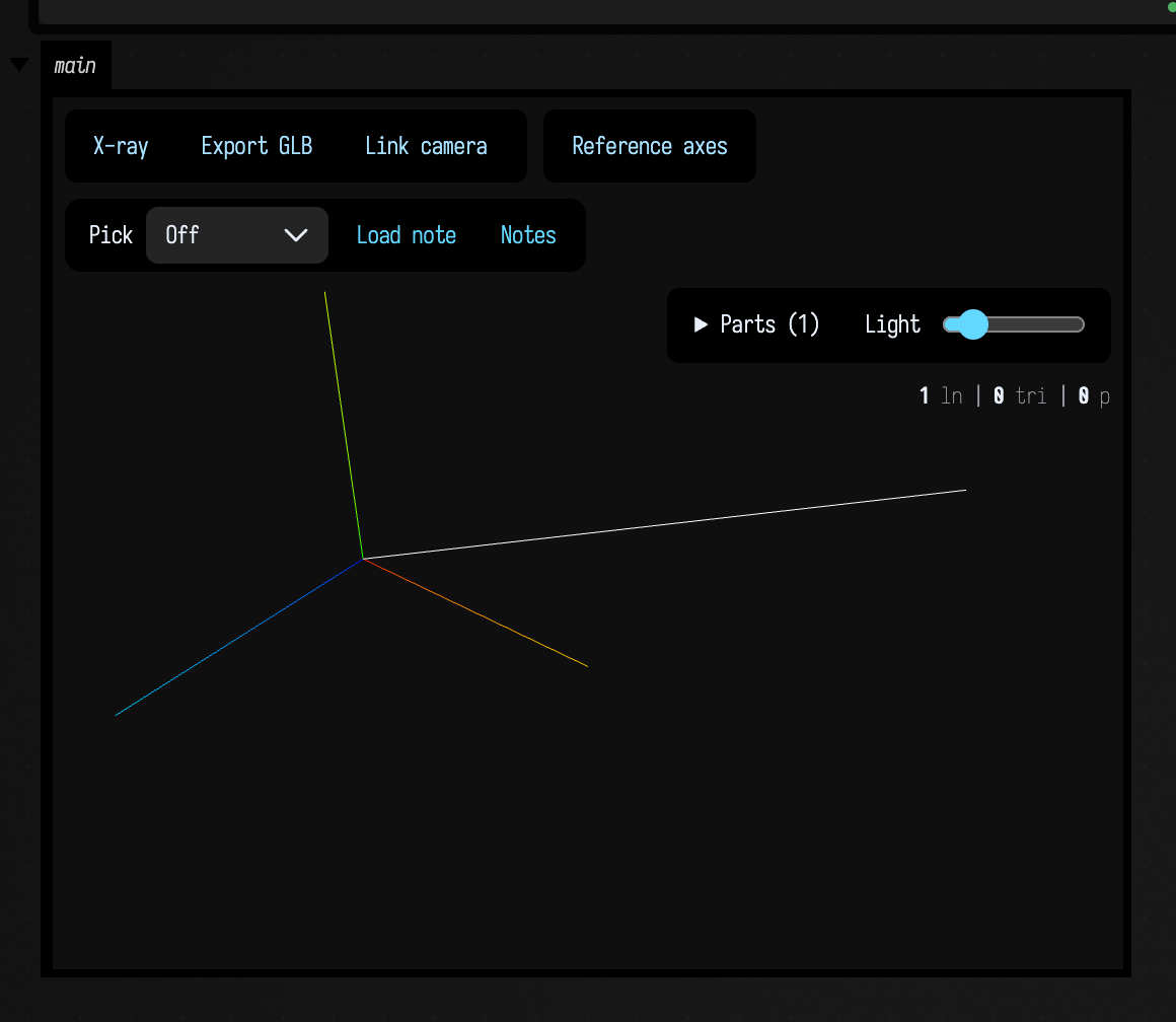
Each module exports a default factory returning a descriptor with a unique id.
mount(context) receives a toolbar element, THREE, the camera and controls,
overlays, the inspector API, sources() and requestRender(). surface is the
viewer canvas for pointer input; interactionBusy() tells an editing tool when
picking or measurement already owns the interaction. Reuse the inspector for
visible-surface picking and leave its camera controls enabled outside a drag.
Tool overlays stay
out of GLB exports. dispose() releases the tool's own GPU resources and listeners;
Field removes its toolbar and overlay group. refresh() runs after the viewer applies
its base pose, rather than on an animation timer. Compute transformations from retained
source coordinates, never by repeatedly transforming the previous result.
If a tool needs asynchronous initialization, return its promise from mount(context).
Field waits for it before restoring tool state or capturing the viewer. A rejected promise
removes the incomplete tool and makes capture report its error. The initial saved state is
recorded after initialization finishes; release listeners and pending work in dispose().
For stateful tools, implement all three methods: snapshot(), validate(state) and
restore(state). State must be finite JSON of at most 32 KB per tool. Views and notes
retain that state. Loading a view that needs an unavailable tool reports an error;
it never imports a module from the note. Older views reset tools to their initial state.
Validation must reject invalid input without mutation; restoration should not fail
once validation has accepted it.
Agents: loading tools in a capture browser
Use FieldViewer.tools.register(descriptor) or
await FieldViewer.tools.load("/path/to/tool.js") in a capture browser. Both return
an idempotent disposal function. FieldViewer.tools.ids() lists installed tools.
After direct registration, await FieldViewer.tools.ready() waits for initialization.
FieldViewer.captureStatus() reports readiness, the geometry revision and any startup error;
readiness includes the tools and a rendered frame, not just a loaded HTML document.
Use the same source geometry revision when restoring a note. An application owns its
modules and their behavior; registration does not validate geometry produced by a tool.
Data colours and late viewers
In a tiled three scene, surface picking uses the camera and viewport of the panel
under the pointer. Click callbacks and hover highlights apply to that panel's objects
(plus objects assigned to every panel); title bands do not pick geometry underneath.
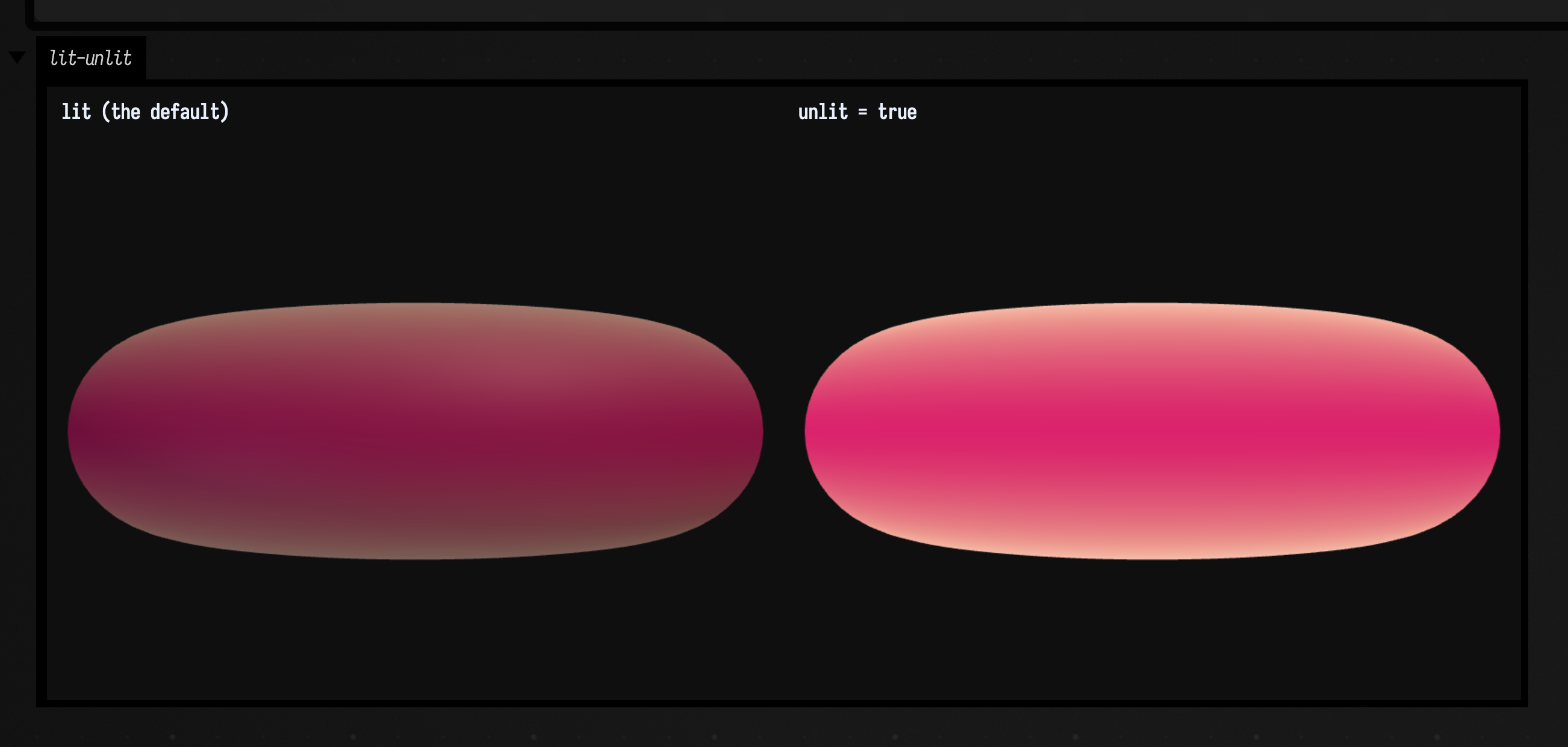
Use mesh(mesh, unlit = true) for force bands or other scalar data: the mesh's vertex
colours are displayed without lighting or tone mapping. The default remains a lit surface. This
example shows the same torus both ways:
:::static
// One torus coloured by its Gaussian curvature, drawn twice: lit on the left, unlit on the right.
val ring = torusMesh(96, 48, 0.62, 0.24)
val curvature = ring.coloredByScalar(ring.gaussianCurvature(), "coolwarm")

three(name = "lit-unlit", channel = "lit-unlit", width = 760, height = 340) {
    columns(2)
    mesh(curvature, panel = 0, wireframe = false)
    mesh(curvature, panel = 1, wireframe = false, unlit = true)
    panel(title = "lit (the default)", bounds = curvature.toThreeBounds())
    panel(title = "unlit = true", bounds = curvature.toThreeBounds())
}
For a smooth surface with per-element colours, compute normals on the connected geometry before duplicating vertices for discontinuous colours; colour boundaries are not creases.
Kotlin display panels are retained by the live box and replayed when a new browser finishes
loading its document. This does not re-run code. The latest panel per channel, explicit
open/close state, and current control values are replayed; cleared panels stay cleared.
Retention is in memory (up to 128 panels and eight million HTML characters per box), not
saved output across a server restart. Older panels are evicted when that budget is exceeded.