Tutorial: Warped rendering tutorial (Field 14)
Say you want to render something using Field's graphics system, but process the output before it goes on the screen? Perhaps you are projecting onto something that isn't flat, or from an odd angle; perhaps you want to composite one rendering with another; perhaps you are building your own passive stereo system and want to merge two views of the same scene into one screen. This page will get you started.
In this dive into Field's graphics system we'll touch upon the following topics:
- Rendering off-screen to something that you can use as a texture map (specifically a Frame Buffer Object)
- Drawing things that you can interact with in 3d using the FLine drawing system.
- Some basic GLSLang shader work in Field.
We'll build and revise the code at each step; if you get lost, or don't fancy copy-pasting the code, you can just download the field sheet here.
Warped rendering
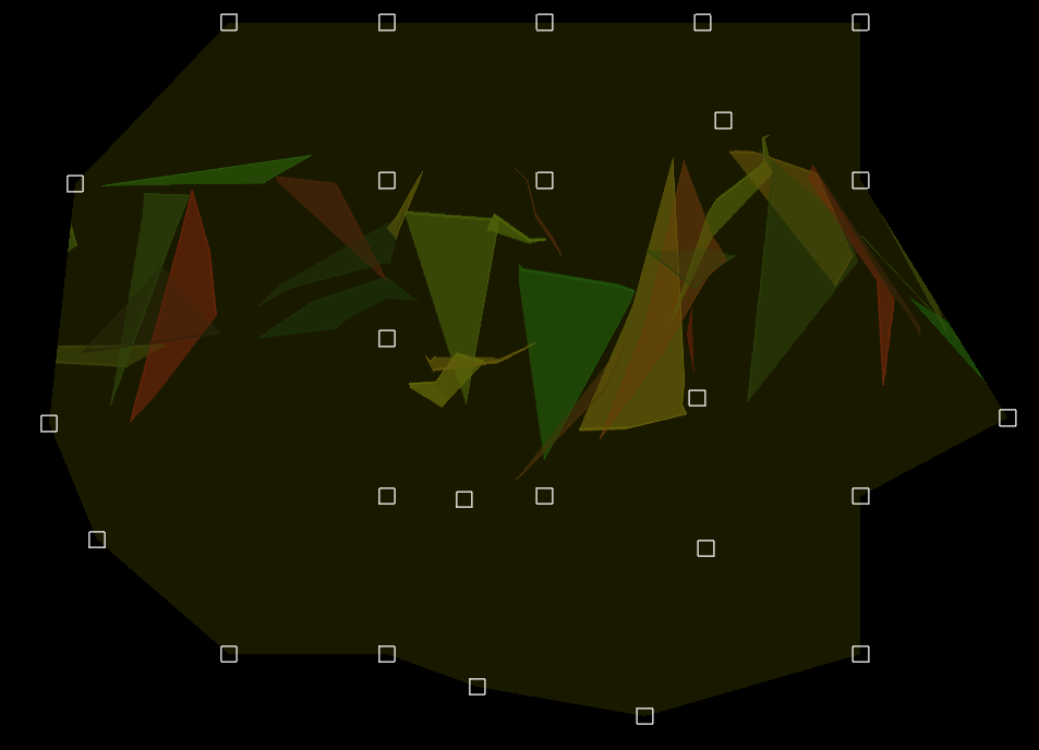
Here's where we are heading:
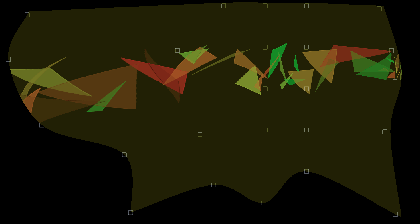
Inside that heavily distorted rectangle, there's a full 3d scene — camera, geometry, shaders, the works. It just happens to be being drawn not to a rectangular screen, but to a warped shape. This shape is defined by the control vertices (those squares) and you can click and drag those shapes around (or modify them in code) to define the warp.
Step 1. Rendering to a Frame Buffer Object
To do this we need to introduce an indirection — we render our scene not to the screen, but to some other area of memory and then use that to texture a piece of geometry. We have a lot of choices about how to do this, but we'll choose the simplest version here. First let's just draw a dark grey square — anybody who has played with the Field graphics system will recognize the default (almost subliminal) shader:
canvas = makeFullscreenCanvas()

shader = makeShaderFromElement(_self)
mesh = quadContainer()

canvas << shader << mesh

with mesh:
    mesh ** mesh ** [Vector3(-1,-1,0), Vector3(1,-1,0), Vector3(1,1,0), Vector3(-1,1,0)]
Note how this connects together — canvas << shader << mesh. The canvas has a shader connected to it (the default one). This shader shades a container for quads called 'mesh', into which we stick a single square. Now Field is drawing:

In a separate box, let's have something much more exciting:
lines = renderShader.getOnCanvasLines(canvas)
lines.submit.clear()

for n in floatRange(0, 40, 100):
    a = Vector3().noise(2)
    b = Vector3().noise(2)
    c = Vector3().noise(2)
    line = FLine().moveTo(*a).lineTo(*b).lineTo(*c)
    line += Vector3(-20+n, 0, 0)
    lines.submit.add(line)
    line(filled=1, color=Vector4(Math.random(),Math.random(), 0, 0.2))

canvas << renderShader
Similar setup, but here we are using the FLine drawing system. Yields:
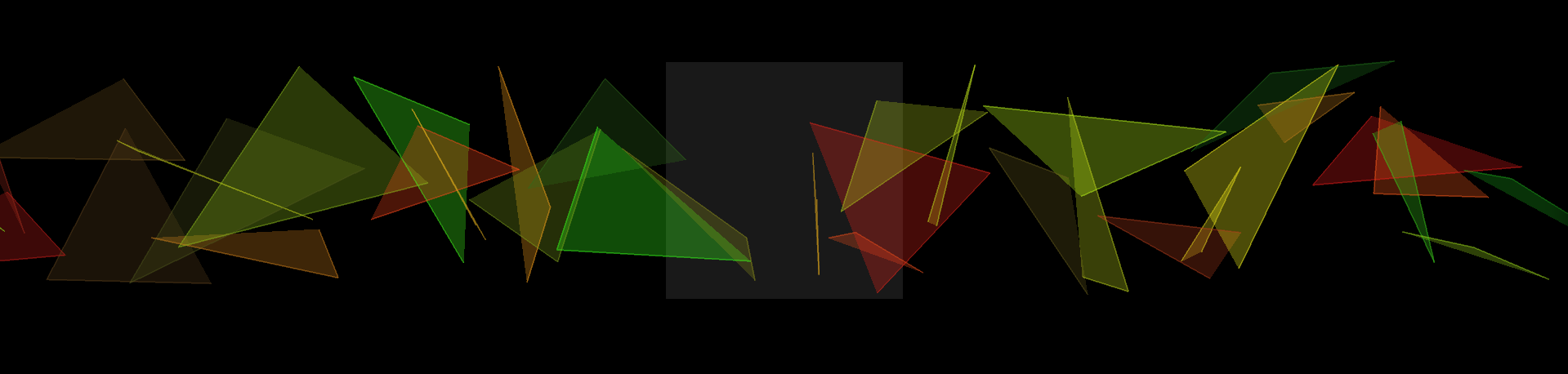
Now, what we really want is to texture that boring grey square with those colorful triangles. First we need a Frame Buffer Object — OpenGL's name for an off-screen drawing area. First we make one:
fbo = makeFrameBuffer(canvas.width(), canvas.height(), useRect=0, genMipmaps=0)
(for a discussion about useRect and other parameters, see here). And then we tell it to update along side the canvas:
canvas ** fbo
BaseGraphicsSystem_FBO explains the ** and << operators in depth.
Next we need to disconnect those colorful triangles from the canvas and put them into that FBO instead:
canvas | renderShader # --- disconnect
fbo.getSceneList() << renderShader # --- connect
You see that they disappear from the canvas completely. They are being drawn, just not to a place that you can see.
Two things remain. First we need to add the FBO as a texture map to the grey square:
shader.theTexture = 0
shader << fbo
That declares that we can use a texture called theTexture in our shader. Let's use it. In our vertex shader:
varying vec4 vertexColor;
varying vec2 texCoord;

attribute vec4 s_Color;
attribute vec4 s_Five;

void main()
{
    gl_Position = gl_ModelViewProjectionMatrix * gl_Vertex;
    vertexColor = s_Color;
    texCoord = s_Five.xy;
}
The plan is to grab our texture coords from channel "5".
The fragment shader will use them to do the texturing:
varying vec4 vertexColor;
varying vec2 texCoord;

uniform sampler2D theTexture;

void main()
{
    gl_FragColor = texture2D(theTexture, texCoord.xy) + vec4(0.1, 0.1, 0, 0);
}
We've added a little dark yellow to the rendering so that we can see the edge of our rendering square.
With texture coords, our geometry code is now:
with mesh:
    mesh ** mesh ** [Vector3(-1,-1,0), Vector3(1,-1,0), Vector3(1,1,0), Vector3(-1,1,0)]

mesh.setAux(0, 5, 0, 0)
mesh.setAux(1, 5, 1, 0)
mesh.setAux(2, 5, 1, 1)
mesh.setAux(3, 5, 0, 1)
We all those things in place we have:
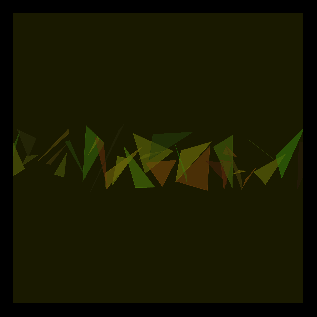
That square is floating in the middle of the canvas. We can cause it to stick itself to the corners of the window instead by changing the vertex shader:
gl_Position = gl_ModelViewProjectionMatrix * gl_Vertex;
should become just:
gl_Position = gl_Vertex;
Now we have our vertex coordinates specified in normalized device coordinates — which is how OpenGL thinks about the screen. Specifically the bottom left corner is '-1,-1' and the top right is '1,1' — note that this is upside down from most windowing systems (that have their origin in the top, since historically, that's where the electron beam that scanned out the display started from), but it's the right way around for most grade-schoolers drawing graphs with squared paper (the x-axis does indeed start in the middle and head to the right, the y-axis does go up).
We've already got our mesh with a square from -1, -1 -> 1,1 so we now cover the whole screen and we're finished with step 1.
Step 2. An interactive mesh warping tool
We've already seen that Field can draw lines and shapes using FLine. Field can also associate event handlers with these shapes to make them interactive. This includes letting you drag them around — even in 3d. Full documentation is here (and an associated "deep dive" is here).
Here's what we need to make a draggable FLine. First a handler:
class SomeHandler(Eventer):
        def __init__(self, line):
                self.on= line

        def down(self, event):
        self.downAt = Vector2(event.x, event.y)
                return 1

    def drag(self, event):
        a, b = self.on.bounds()
        center = (a+b)*0.5

        # --- begin 3d math
        projector = canvas.camera.getProjector()
        p1 = projector.toPixel(center)
        p1 += Vector3(event.x-self.downAt.x, -(event.y-self.downAt.y),0)
        centerNext = projector.fromPixel(p1.x, p1.y, center)
        # --- end 3d math

        self.on+=centerNext-center
        self.on.forceNew=1
        self.downAt = Vector2(event.x, event.y)
The critical part here is the part marked '3d math'. Let's go through it line by line:
* projector = canvas.camera.getProjector() — a projector is a convenience class in Field to help you move between world space (the space that you specify geometry in) and pixel space (the space of screens, and, as it happens, frame buffer objects.
* projector.toPixel(center) — this gives us the pixel location of where the center of the FLine appears
* p1 += Vector3( ... ) — this moves the center by the amount that the mouse has moved in screen space — watch for that minus sign on the 'y' axis (see the explanation above).
* projector.fromPixel( ... ) — this converts back again from pixels back out into world space (the space where geometry lives).
Why three parameters to fromPixel because when we convert from world (3d) space to pixel (2d) space we lose information. A pixel actual represents a whole infinite ray poking out of the screen at that point. When we convert back from pixels where along that ray do we want? The 3rd parameter rids us of this ambiguity — we want the point on this ray that's closest to where the FLine used to be.
Now let's draw our UI:
dragShader = makeShaderFromElement(_self)
canvas << dragShader

lines = dragShader.getOnCanvasLines(canvas)
lines.submit.clear()

vertexPositions = {}
numDivisions = 5

w = 0.1
for x in range(0, numDivisions):
    for y in range(0, numDivisions):
        ll = FLine().rect(x-w/2, y-w/2, w, w)
        ll.containsDepth=1
        ll.eventHandler = SomeHandler(ll) # --- adds our event handler
        lines.submit.add(ll)
        vertexPositions[x,y] = ll
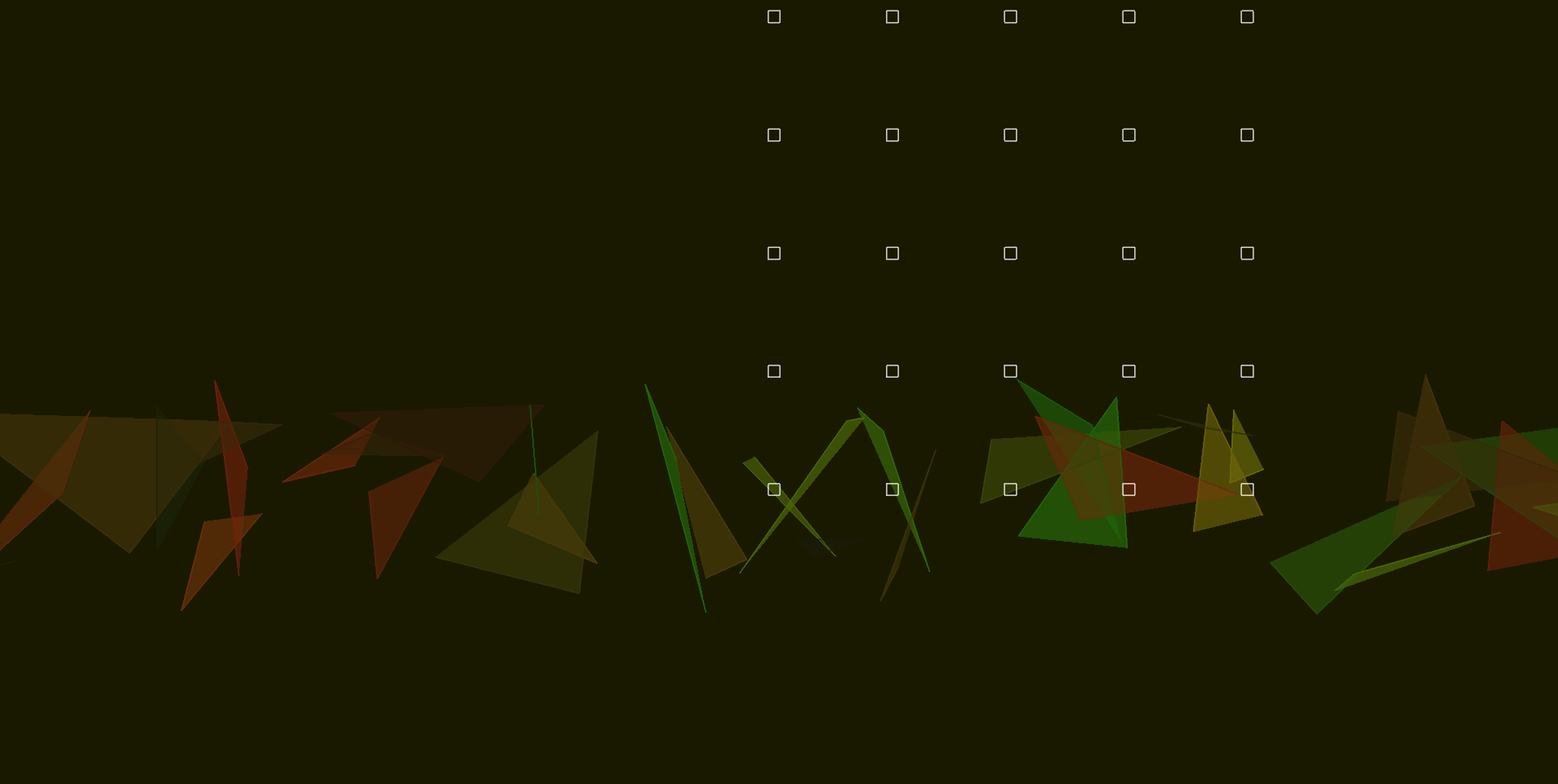
A quick check will prove that these lines are in fact draggable.
One last move remains — connect these lines with the mesh itself. Let's put this in its own box:
from __future__ import division

def up():
    def center(line):
        a,b = line.bounds()
        c = (a+b)*0.5
        ndc= canvas.camera.getProjector().toPixelNDC(c)
        return ndc

    with mesh:
        for x in range(0, numDivisions):
            for y in range(0, numDivisions):
                a = mesh ** center(vertexPositions[x,y])
                mesh.setAux(a, 5, x/numDivisions, y/numDivisions)

        for x in range(0, numDivisions-1):
            for y in range(0, numDivisions-1):
                mesh ** [x*numDivisions+y, (x+1)*numDivisions+y, (x+1)*numDivisions+(y+1),x*numDivisions+(y+1)]


_r = up
We've wrapped this update code in its own function and written _r = up. This tells Field that we can "run" this box. When we do so (say, by option-clicking on the box, or command-page up) we connect the UI to the warp mesh and we can drag the mesh around in real time. The following code, also in its own box, will give the FBO its own 3d animated camera and remove all doubt that the contents inside is in 3d:
camera = BasicCamera()
fbo.getSceneList() << camera

camera.width=canvas.width()
camera.height=canvas.height()
camera.aspect=canvas.width()/(canvas.height()+0.0)

def animateCamera():
    s = camera.getState()
    s.position = Quaternion(s.up, 0.01).rotateVector(s.position-s.target)+s.target
    camera.setState(s)

_r = animateCamera
Improvements
- The downloadable sheet also includes code for doing a bicubicly interpolated surface that's a lot smoother as well; there's nothing particular to Field to it.
- This is pretty much how I would code this if I needed to modify the warp very infrequently (for example during setup of an artwork, but not during its actual running). If I wanted to control the warp live, I'd generate the warp on the GPU as well — using another FBO to contain the result. This would give me a live-controllable bicubic warp at a sensible frame-rate, but it would give this tutorial another level of indirection.
- Depending on what I was going to do with the output, I'd definitely consider super-sampling the underlying FBO before putting it on the screen; I might go so far as to compute a per-vertex blur-radius in texture space based on how distorted the warp is. If you are looking for a little more quality for no effort you can add
genMipmaps=1to your call tomakeFrameBuffer.