
‘Shaders’
Field, like all other high performance graphics-making environments, offers a window onto the essentially hybrid nature of modern computing — specifically that there are two computers inside your computer. One that’s dedicated to doing ‘general purpose things’ and one that’s dedicated to doing ‘graphics things’. Somewhere around 2003 or so, the complexities of describing those ‘graphics things’ — textures, transforms, lighting, materials — broke down. The architecture that had been built around the CPU setting modes and options (switches and dials) for the graphics hardware become untenable and was largely rejected in favor of the CPU compiling and sending whole programs — called shaders — to the graphics hardware.
Fortunately sending code off to be executed is actually exactly what Field is built for.
First some structure and terminology. Unlike the JavaScript that Field is immediately oriented towards there are 3 different carefully defined ‘places’ once can interpose computation inside the graphics pipeline. You can think of these places as running ‘on’ vertices which in turn get packaged together into ‘primitives’ (say, a triangle, a line or a point) which in turn end up causing pixels to be colored. OpenGL (the graphics interface that we’re using here) calls these ‘vertex’ programs, ‘geometry’ programs and ‘fragment’ programs (fragment being an obscure, but technically more correct, term here for pixel). Field is already using a program at each of these stages to draw everything you seen (not just the contents of Stages, but also the boxes, the text editor etc.); you can start with these shaders and edit them.
Field is an excellent place for hacking on shaders; Field’s documentation is far from the best place for learning about them. We’ll just cover the facts that are Field dependent.
Places to start: the book of shaders (which is half finished but still great), http://www.iquilezles.org/www/index.htm (which shows the kinds of images you can make with nothing more than lots of grade-school math) and https://www.shadertoy.com/ (an interactive playground for writing shaders with a wonderful community).
Then of course there’s the reference information: https://www.khronos.org/opengl/wiki/Shader. This goes over other kinds of programs, located in other stages of the graphics pipeline (don’t worry, they are hardly used). As you Google, one word of warning: we’ll be using version 320 and above of GLSL (The GL Shader Language). This is the latest version. Earlier versions are fairly different and there’s some documentation going around that’s for older versions..
Finally, a word of caution: writing shaders can be a frustrating exercise — it’s very easy to draw nothing, the error messages aren’t always helpful, and you are much closer to the hardware than you normally are (you might even be able to write some code that draws something so complex that you have to restart your computer…)
Hello Triangle (shader)
Let’s start with a triangle:
Just a triangle
var layer = _.stage.withName("some layer")

var f = new FLine()
f.moveTo(30,30).lineTo(60,60).lineTo(33,62)

// let's just fill it
f.filled=true
f.stroked=false

// and make it white
f.color=vec(1,1,1,1)

layer.lines.f = f

// keep redrawing the screen
while(_.stage.frame());
Yields:
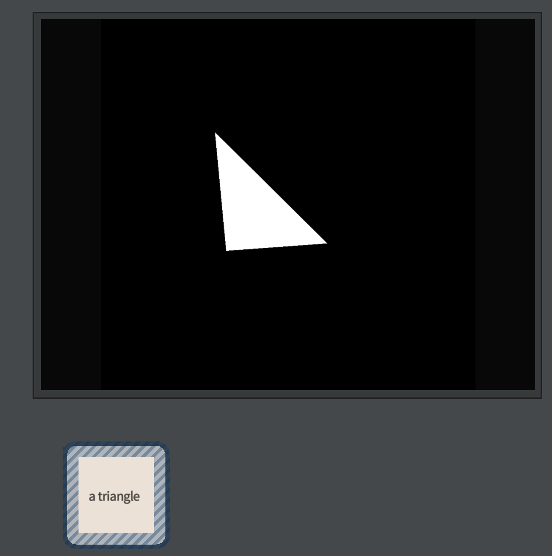
We might ask ourselves, though, if we were being particularly curious, why this ends up as a white triangle in the middle of the stage. Certainly there’s a triangle being sent to the graphics card, made up of three vertices (with positions) and surely the Vec4 (1,1,1,1) is being sent somewhere as well. But who has decided to make that result end up with those exact pixels turning white?
Let’s expose the hidden power:
The magic command that opens up the shader of a layer stage
var shader = layer.bindTriangleShader(_)That call tells Field that we’d like to edit the shader programs associated with layer in this box (that’s what the ‘_’ means). If you call bindTriangleShader you get to edit the shader associated with the filled parts of FLines; for the stroked parts call bindLineShader, and for points call bindPointShader. Each kind of primitive uses a different set of shaders.
Once we’ve done that we’ll discover that, in addition to the JavaScript that’s in this box, there are three other pieces of code associated with this box. You can switch between them with the control-space menu in the text editor:
We can select ‘edit vertex’, ‘edit geometry’ or ‘edit vertex’ to edit one of those programs. You can ‘edit code’ to get back to JavaScript. Unlike JavaScript, these programs aren’t the kinds of things that you can execute partially — you can’t select a few lines and just run those. Nor can you ‘print’ the values of any variable. As print suggests the very idea of displaying a variable harks back to the days where computers had printers, not screens. The GPU is a long way from that kind of heritage.
Here’s an edited down version of the default triangle shader for Stage in Field. This has been simplified to help you understand the structure, but hopefully not too much.
This vertex shader is part of a trio of codes that’s executed in Field for every (triangle) on the stage
#version 410
// that was the version number, it has to be on the first line

// here are the attributes that we expect geometry to have for every vertex
// this is the convention used by Field. You can associate other per-vertex things
// through calls to various methods on FLine
layout(location=0) in vec3 position;
layout(location=1) in vec4 color;
layout(location=2) in vec2 pointControl;

// these are the things that come _out_ of this stage
out vec2 pc_q;
out vec4 vcolor;

// these are things that are sent per-FLine not per-vertex
// Field sets them all for you under the hood
// they are options for various cameras that Stage support
uniform vec2 translation;
uniform vec2 scale;
uniform vec2 bounds;
uniform float displayZ;

uniform mat4 P;
uniform mat4 V;

uniform vec2 rotator;

void main()
{
    id = gl_InstanceID;

    // this is the transformation that gets FLines to sit inside the 100x100 Stage
    vec2 at = ((position.xy+vec2(0.5,0.5))+translation.xy)/bounds.xy;
    gl_Position =  vec4(scale.x*(-1+at.x*2)+displayZ*position.z, scale.y*(-1+at.y*2), position.z, 1.0);
    gl_Position.xy = vec2(rotator.x*gl_Position.x + rotator.y*gl_Position.y, -rotator.y*gl_Position.x + rotator.x*gl_Position.y);

    // and then a camera transformation
    // a 'V'iew matrix followed by a 'P'rojection matrix
    mat4 effectiveTransform = P*V;
    vec4 effectivePosition = gl_Position;

    // gl_Position is the output for where the vertex is going to end up
    // at least until it gets to the Geometry Shader
    gl_Position = effectiveTransform*effectivePosition;

    // pass on the per-vertex pointControl and vertex color information to the
    // next program
    pc_q = pointControl;
    vcolor = color;
}
You might find that this shader is more complex than this — in particular stereo and VR rendering adds some complexity here — but you should be able to map the structures together in your head. In total, this vertex program is taking each vertex of every (triangle) you draw on this layer and warping that coordinate system such that Stage is a 100x100 thing, and then giving you some additional camera options on top of that.
You should also note that the language, while a little like JavaScript (and a lot like C) isn’t. It’s GLSL — it’s its own thing. There are lots of things that you can’t do here: there are no variables that live for any length of time outside functions, everything is wiped clean once main() ends. There is no communication between vertices in the vertex shader, between primitives in the geometry shader, or between pixel shader. And there certainly isn’t anything that goes from the GPU back to the CPU. There are ways around each of these limitations, but they can be byzantine.
Finally, the best way to understand this code might be to get in there and change it. At the end (before the closing }) add:
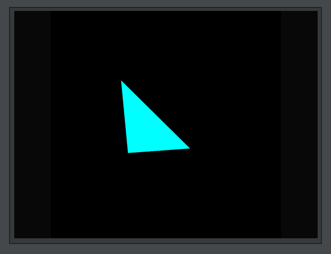
vcolor.r = 0.0;Then you and recompile and upload your code to the graphics card with ctrl-space ‘reload shader’. If you don’t get any errors, you’ll see:
If you don’t have any code running _.stage.frame() you might need to click on the canvas to cause Field to redraw to see your changes
You can also hack alterations into gl_Position (to move things around). Remember this code is being executed for every vertex (in every triangle).
If we look at the geometry shader (again, the ctrl-space menu):
This geometry shader runs after the vertex shader for every triangle
#version 410
// declaration of thin kinds of primitives that we expect (triangles)
layout (triangles) in;
// and the kind that this thing yields (strips of triangles)
layout (triangle_strip) out;
// no more than 3 vertices though
layout (max_vertices = 3) out;

// this program gets all three values of vcolor
// at the same time, one for each vertex in the triangle
in vec4[] vcolor;

// and it emits an 'ovcolor' with every vertex in the resulting triangle-strip
out vec4 ovcolor;

void main(void)
{
    int i;

    // I've written this as a loop so that the same code
    // works for lines and points
    for (i = 0; i < gl_in.length(); i++)
    {
        gl_Position = gl_in[i].gl_Position;
        ovcolor = vcolor[i];
        EmitVertex();
    }

    EndPrimitive();
}
For line and triangles in Field this shader is a lot less interesting than the vertex shader. It’s where you’d turn lines into triangle strips, or make little hatching marks (out of lines) for every point. In fact, a custom geometry shader is what Field uses to draw points — each point (which is a single vertex) — gets turned into a little rectangle (made out of two triangles) in the geometry shader. See the section below on points for more details.
For triangles. this stage of the pipeline is the only place where you can see the whole triangle at the same time. Consider trying to write a vertex shader that shrinks each triangle — you can’t. Each invocation of the vertex shader doesn’t know about the others. Only in the geometry shader can you access all three vertices together. In general there isn’t anything that you can do in a vertex shader that you can’t do in the geometry shader, but the vertex shader came first, and might well run faster (since all verticies can be computed at the same time, while geometry shaders only offer triangle-level parallelism).
Finally, the fragment (read pixel) shader:
This fragment shader runs after the geometry shader on every pixel invovled in any triangle
#version 410
// this is where we put our color
layout(location=0) out vec4 _output;

// incoming from the geometry shader
in vec4 ovcolor;

// set by layer.opacity in Field
uniform float opacity;

void main()
{
	_output = ovcolor;
	_output.w *= opacity;
}
That’s it. Nothing much to it — color the pixel by the color that came from the vertex (interpolated across the face of the triangle).
Shaders for textured and video layers are more interesting — this is where we do texture lookup and interpolation based on, per-vertex texture coordinates.
A few notes:
-
Consider the coordinate systems of positions as they move from program to program. As they come into the vertex program they are in some kind of ‘world’ space (the abstract 100x100 space of the
Stageor, in VR, ‘meters’). After they have been multiplied by the camera transforms they are in Clip Coordinates — where x and y correspond to left/right, up/down on the screen itself. This transformation happens in our vertex shader (although it could happen as late as the geometry shader). These clip coordinates are turned into a set of pixels that need to be drawn. By the time the fragment shader runs the only coordinate left is that of the pixel. -
If you are going to mess with positions after they have been transformed by the camera transform you’ll want to understand why they are
vec4notvec3. Or perhaps you are simply intruiged by the use of avec4to storegl_Positionand do some of the camera transforms, start here -
GLSL uses suffixes
xyzwandrgbainterchangably to address components of vectors._output.ais the same as_output.w.
How points are drawn in Field
Field uses the geometry shader to draw points as rectangles (made out of two triangles spanning four vertices). Points come into the vertex shader, pass through it and enter the geometry shader at which point the geometry shader emits triangles. Then the fragment shader carefully draws these triangles in such as way as to make it look like there’s a circle there instead. This is the ‘contemporary’ way to draw points and gives you complete control over their width (and texturing / shape).
So the vertex shader for points is very similar; it’s the geometry shader where things start to get interesting:
This is the geometry shader for ‘points’
#version 410
// points come in
layout (points) in;
// but strips of _triangles_ come out
layout (triangle_strip) out;
layout (max_vertices = 4) out;

// colors come in (this is still a vec4 array even though there's only one
// vertex in a point
in vec4[] vcolor;
out vec4 ovcolor;

// the vertex shader also passes through a 'pc_q' for per-point
// size control. We only use the .x component
in vec2[] pc_q;

// we'l also pass out a 'texture coordinate' for each vertex of the
// rectangle
out vec2 pc;

void main(void)
{

    gl_Position = gl_in[0].gl_Position;

    // Google 'homogeneous coordinates' if you want to know where the gl_Position.w comes from here
    // or take it on trust
    // or try it without it and see if you can figure out what's missing
    vec2 r = gl_Position.w*pc_q[0].x*vec2(1,1)/100;

    gl_Position = gl_in[0].gl_Position + vec4(-r.x, -r.y, 0, 0);
    ovcolor = vcolor[i];
    pc = vec2(-1,-1);
    EmitVertex();

    gl_Position = gl_in[0].gl_Position + vec4(r.x, -r.y, 0, 0);
    ovcolor = vcolor[i];
    pc = vec2(1,-1);
    EmitVertex();

    gl_Position = gl_in[0].gl_Position + vec4(-r.x, r.y, 0, 0);
    ovcolor = vcolor[i];
    pc = vec2(-1,1);
    EmitVertex();

    gl_Position = gl_in[0].gl_Position + vec4(r.x, r.y, 0, 0);
    ovcolor = vcolor[i];
    pc = vec2(1,1);
    EmitVertex();

    EndPrimitive();
}
We’ve left out a few things related to VR and Stereo to better show the actual structure here. Ultimately we build a rectangle of width and height 2/100.0 around each point. By emitting four verticies (in this order) we build two triangles (as part of a ‘triangle strip’) with the four corners of the rectangle. By changing the variable r we can change where and how big the point is (note that, for 100,000s of points, drawing the point so big that it covers the screen can still crash your whole computer — covering the whole screen 100,000 time is still a lot of computation, even today).
What is happening with pc — which is set to -1,-1 in one corner of the rectangle and then 1,-1, -1,1 and finally 1,1 in the remaining vertex? To see what happens we need to look at the fragment shader:
This is the fragment shader for ‘points’, which are now pairs of triangles making a square
#version 410
layout(location=0) out vec4 _output;

// color comes in from the geometry shader
in vec4 ovcolor;

// 'corner coordinate' from the geometry shader
in vec2 pc;

// layer opacity turns up here
uniform float opacity;

void main()
{
	_output  = ovcolor.xyzw;
	_output.w *= opacity * smoothstep(0.1, 0.2, (1-(length(pc.xy))));
}
What’s happening with smoothstep(0.1, 0.2, (1-(length(pc.xy))))? Let’s brake it down:
length(pc.xy) is an expression that will vary from √2 in one of the corners of the rectangle to 0 in the dead middle of the rectangle. Crucially pc.xy is interpolated across the face of the triangle being drawn. You might want to take a moment with some square paper to convince yourself that half way along the long edge of either of the two triangles making up our rectangle length(pc.xy) is exactly 0.
1-length(pc.xy) goes from -0.414 or so in the corner of the rectangle or, 0 in the middle of the edges of our rectangle to 1 in the center of the rectangle.
smoothstep(0.1, 0.2, x) is a function that goes from 0 when x<0.1 to 1 when x>0.2, and does so smoothly.
Putting this all together (again, perhaps with some graph paper), you’ll see that this function goes from 0 outside a oval that’s 0.1 or less from the edge of the rectangle to 1 when it’s 0.2 or more from the edge of the rectangle. For squares this fuction is 1 inside a circle and 0 outside the circle with a little bit of fuzziness on the edge (to stop the pixels showing up).
This is how you draw a circle in the fragment shader. In a sense, this is a piece of mathematics that is set ‘just right’ for the context of a fragment shader, that results in a circle. If you want to see the results of thinking (and practicing) over the problem of what else one can draw with a single piece of math in a fragment shader, take a look here.
More Uniforms
In all the stages you’ll see declarations like:
uniform vec2 scale;This tells GLSL that there’s a variable called scale that’s a vec2. It is uniform across all invocations of the program after they have been launched. Whatever that scale happens to be for that whole piece of geometry (that FLine or mesh, or the whole shader itself) it doesn’t change. Field sets a whole bunch of these for you. You’ll almost certainly want to add your own.
Let’s add an offset to everything we draw. In the vertex program add at the top:
uniform vec3 wobble;And, before the camera transform:
effectivePosition.xyz += wobble.xyz;You should find that, upon reload, absolutely nothing happens. wobble, unset, defaults to (0,0,0). To set it, set it from JavaScript:
var shader = layer.bindTriangleShader(_)
shader.wobble = vec(0,0,0).noise(1)
Your triangle will move randomly, once:
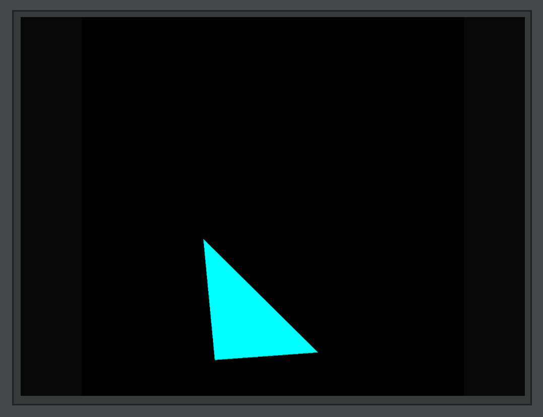
You’ve sent a value of wobble from the CPU to the GPU. This hasn’t taken much time, space or CPU power and yet, it might change every single vertex that you draw (in the layer). This is, for example, how light positions and colors end up being sent to the shaders that build computer games. To send a different random number every frame you can put shader.wobble = ...something... inside your animation loop. Alternatively you can write:
shader.wobble = () => vec(0,0,0).noise(1)Then:
This is a convention in Field for setting uniforms. You can set the uniform to a number, a Vec2, a Vec3 or a Vec4 (commonly made using vec(x,y), vec(x,y,z) or vec(x,y,z,w)) or you can set it to a function that returns the same. This function will get called every animation frame. This extra indirection lets you write:
var noise = vec(0,0,0).noise(1)

// ...

shader.wobble = () => noise
And now your JavaScript code can happily set noise and it’s value will be automatically sent to the GPU.
Less Uniform
uniform variables are applied to the whole piece of geometry. How can you limit their effect to certain vertices? After all the whole point of this partitioning drawing into these stages (the GPU in the class computer likes to run thousands of vertex programs at the same time for example).
Some creative possibilities:
gl_VertexIDgives you a ‘number’ associated with vertex, starting at 0.- inspect
colorand do something only to the vertices that have, say,color.r>0.8? - in the fragment shader you can ask for the pixel that you are drawing (
gl_FragCoord.xy, in actual pixels). - base things on space (
effectivePosition.x<0?)
Alternatively, you might need something that’s more ‘per-vertex’ than `per-invocation’. Try (in the vertex program):
layout(location=5) in vec2 awesome;Then, in Field, you can write:
var f = new FLine()
f.addAuxProperties(5, "awesome")

f.moveTo(30,30)
f.node().awesome = vec(0,0)
f.lineTo(60,60)
f.awesome = vec(0,0)
f.node().awesome = vec(1,0)
f.lineTo(33,62)
f.awesome = vec(0,0)
f.node().awesome = vec(0,1)
This associates a vec2 with each vertex. Inside the vertex program you can use awesome like a uniform, except it contains the values you specify per-vertex. This is, in case you are wondering, how point size works, vertex colors and texture coordinates.
VR Notes
Some notes about the shaders for VR.
-
The central trick in VR is to render everything twice slightly differently — once for each eye. There’s some emerging support for faster ways of doing this, but the main approach is to simply render everything twice. You’ll see code in the ‘real’ shaders for VR capable Field that messes with the clip coordinates based on which eye we’re drawing.
-
Each eye also gets its own slightly different camera transform which is, traditionally, sent as a
Projectionmatrix and aViewmatrix — thing focal length of the lens (projection) and where the lens is (view).